Because RFL™ and Hubbell® have a policy of continuous product improvement, we reserve the right to change designs and specifications without notice.
RFL DA-91I RFL Electronics Inc.
March 6, 2002 5 (973)
334-3100
1
2
3
4
5
6
7
8
9
10
15
12
13
11
14 16 30 24 22
31 23 25
17 26 28 18 20 21 19 29 27
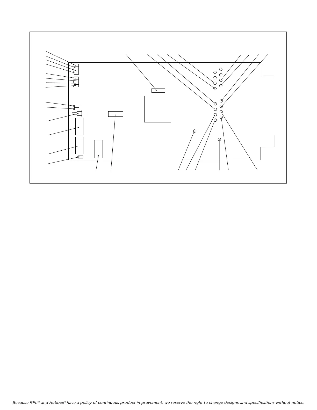
Figure 2. Controls and indicators, RFL DA-91I Asynchronous Data Polling Channel Module
9. Select Bus direction by using DIP switches SW2-7 and SW2-8.
Place SW2-7 in the DOWN position to transmit in the B direction and receive from
the A direction. Place SW2-7 in the UP position to disable the B Bus.
Place SW2-8 in the DOWN position to transmit in the A direction and receive
from the B direction. Place SW2-8 in the UP position to disable the A Bus.
10. Set DIP switch SW3-1 to select one channel or two channel operation..
Place SW3-1 to the ON position to select one channel operation
Place SW3-1 to the OFF position to select two channel operation
11. Set DIP switch SW3-2 to turn on CTS1.
Place SW3-2 to the ON position to turn on CTS1 at all times
Place SW3-2 to the OFF position to make CTS1 operate as a function of RTS1
12. Set DIP switch SW3-3 to turn on CTS2.
Place SW3-3 to the ON position to turn on CTS2 at all times
Place SW3-3 to the OFF position to make CTS2 operate as a function of RTS2
13. Set DIP switch SW3-4 to enable 7-bit sampling.
Place SW3-4 to the ON position to use 7 bits for sampling in single mode and 1
signaling bit. In dual mode it will enable 2 signaling bits.
Place SW3-4 to the OFF position to use 6 bits for sampling in single mode and 1
signaling bit. In dual mode it will enable 1 signaling bit.
>> text continues on page 8 <<