Because RFL™ and Hubbell® have a policy of continuous product improvement, we reserve the right to change designs and specifications without notice.
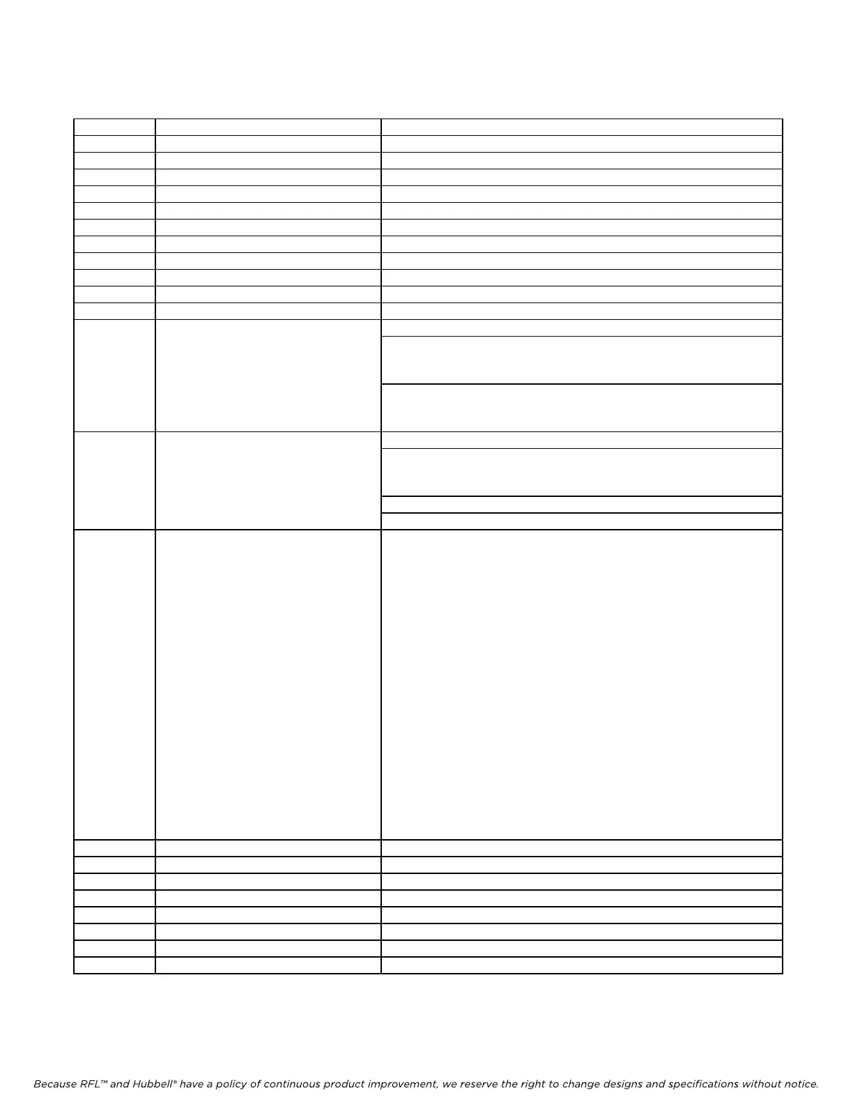
Table 2. Controls and indicators, RFL DA-91I Module
Item Name/Description Function
1 CH1 RTS LED (green), DS2 Lights when Channel 1 RTS (Request To Send) is active
2 CH1 TX LED (green), DS3 Lights when Channel 1 is transmitting
3 CH1 RX LED (green), DS4 Lights when Channel 1 is receiving
4 CH1 RLSD LED (green), DS5 Lights when Channel 1 RLSD (Receive Line Signal Detect) is active
5 CH2 RTS LED (green), DS10 Lights when Channel 2 RTS is active
6 CH2 TX LED (green), DS11 Lights when Channel 2 is transmitting
7 CH2 RX LED (green), DS12 Lights when Channel 2 is receiving
8 CH2 RLSD LED (green), DS13 Lights when Channel 2 RLSD is active
9 LOC LB LED (red), DS18 Lights when module is in Local Loopback mode
10 REM LB LED (red), DS19 Lights when module is in Remote Loopback mode
11 Service LED (green), DS1 Lights when service is ON
12 DIP Switch, SW1 SW1-1 to SW1-6 Selects SCB Address (See Table 3)
SW1-7 Selects Local or Remote control
UP = Local Control
DOWN = Remote Control
SW1-8 Selects module service ON or OFF
UP = Service ON
DOWN = Service OFF
13 DIP Switch, SW2 SW2-1 to SW2-5 Selects Time Slot (See Table 4)
SW2-6 Selects CAS ON or OFF
UP = CAS ON
DOWN = CAS OFF
SW2-7 Selects transmit on B receive on A
SW2-8 Selects transmit on A receive on B
14 DIP Switch, SW3 SW3-1 Selects one channel or two channel operation
ON = one channel operation
OFF = two channel operation
SW3-2 Enables CTS1
ON = CTS1 on at all times
OFF = CTS1 a function of RTS1
SW3-3 Enables CTS2
ON = CTS2 on at all times
OFF = CTS2 a function of RTS2
SW3-4 Enables 6 or 7 sampling bits
ON = Enables 7 sampling bits (Used when DA-91I is
interfaced with another DA-91I.
OFF = Enables 6 sampling bits (Used when DA-91I is
interfaced with a DA-91.
SW3-5 Time slot sharing
ON= Time Slot Sharing is enabled.
OFF= Time Slot Sharing is disabled (Normal
Operation).
(See P
aragraph 14 of Installation Section for
more information)
15 Toggle Switch, SW4 Selects Local Loopback, Normal, or Remote Loopback
16 Jumper array, J1 For factory use only
17 Jumper J2 For factory test only using ACTEL Probe
18 Test point, TP1 Channel 1 TX local data
19 Test point, TP2 Channel 1 RTS bit
20 Test point, TP3 Channel 2 TX local data
21 Test point, TP4 Channel 2 RTS bit
22 Test point, TP9 Channel 1 CTS bit
RFL DA-91I RFL Electronics Inc.
March 6, 2002 6 (973)
334-3100