Because RFL™ and Hubbell® have a policy of continuous product improvement, we reserve the right to change designs and specifications without notice.
FUNCTIONAL DESCRIPTION
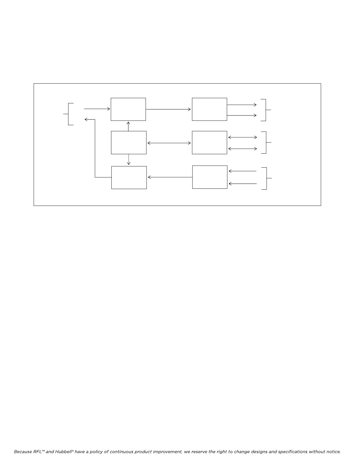
Figure 3 is a functional block diagram of the RFL DA-91I module. It is provided to familiarize the user
with the RFL DA-91I’s signal flow and interfacing. The figure shows signal flow in the transmit and
receive modes of operation.
RS-232 TX
DATA I/O
PORT 1 * RX
MULTIPLEXER
TIMING
DEMULTIPLEXER
BUFFER
BUFFER
ADDRESS
SELECTION
TO TRANSMIT
DATA BUS
TO/FROM
CHANNEL
ADDRESS
BUS
FROM RECEIVE
DATA BUS
A
B
A
B
A
B
* DATA I/O CONNECTIONS ARE SHOWN FOR PORT 1 ONLY. CONNECTIONS FOR PORT 2 ARE THE SAME.
Figure 3. Functional block diagram, RFL DA-91I module.
The RFL DA-91I can provide one or two full duplex channels between an unlimited number of
locations using a single 64 kbps DS0 time slot. It can be used in IMUX 2000 Terminal or Drop/Insert
multiplexers. The data channels are interfaced to the RFL DA-91I through the MA-402I Module
Adapter. A cable adapter plugs into the MA-402I to provide a 9-pin D-subminiature (DB-9S)
connector for each channel. Each 9-pin connector is wired in a standard RS-232 configuration, as
shown below, and is labeled to show the corresponding channel on the RFL DA-91I.
Receive Data (RxD) Pin 2
Transmit Data (TxD) Pin 3
Ground Pin 7
Connections to and from the RFL DA-91I is accomplished through an edge connector on the module,
the motherboard bus, and an RS-232 interface to the IMUX 2000 control and monitor modules. The
received data contains the data extracted from the T1 line, and the transmit data contains the data to be
inserted into the T1 line. Transmit and receive bus directions and time slot selections are independently
selectable by DIP switches SW1 and SW2.
The RFL DA-91I supports Tx Data, Rx Data, Receive Line Signal Detect, Request to Send, Clear to
Send, Data Set Ready and Signal Ground. Once the control signals have been established, the
transmitted data is sampled at 8 kHz in 4.8 or 9.6 kbps per channel. This data is multiplexed and
inserted into the T1 line. The received data from the T1 line is demultiplexed, separating the data
through the interface. The asynchronous data is decoded, retimed, and sent through one or two RS-232
interfaces for distribution.
RFL DA-91I RFL Electronics Inc.
March 6, 2002 10 (973) 334-3100