Because RFL™ and Hubbell® have a policy of continuous product improvement, we reserve the right to change designs and specifications without notice.
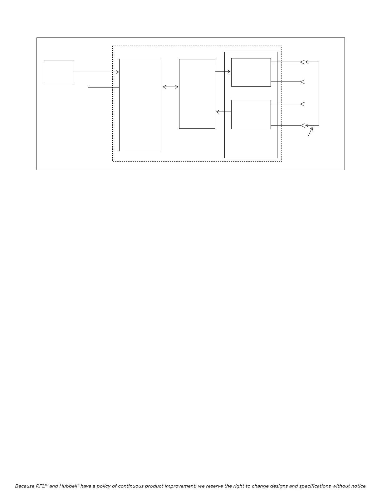
CH1
CH2
RS-232
BIT ERROR
TEST SET
MA-402I
MODULE
ADAPTER
IMUX 2000 DROP/INSERT MULTIPLEXER
RFL DA-91I
TRANSMIT
RECEIVE
COMMON
MODULE
DS1-A
EQUIP
OUT
DS1-B
EQUIP
OUT
DS1-A
EQUIP
IN
DS1-A
EQUIP
IN
LOOP
TEST CABLE
Figure 5. Simplified block diagram, first part of loop test for RFL DA-91I modules installed in
drop/insert multiplexers.
4. Check the CH1 Transmit and CH1 Receive activity LEDs on the front panel of the DA-91I
module. See Figure 2 and Table 1 for locations.
Both activity LEDs should NOT be lit.
5. Connect the BIT Error Test Set to the CH1 RS-232 connector on the cable assembly connected
to the Module Adapter for the RFL DA-91I module under test.
At this point, the equipment should be connected as shown in Figure 5.
6. At the test set, apply power and initialize the Request To Send (RTS) signal, and set its output
to 4.8 kbps for dual mode and to 9.6 kbps for single mode. Check the CH1 Transmit and CH1
Receive activity LEDs on the front of the RFL DS-91I.
Both activity LEDs should be ON, and the RLSD LEDs should correspond to the
proper mode of operation to indicate the reception of the signaling bits.
7. Check the error count on the receive side of the test set.
The error count should be zero.
8. Repeat steps 3 through 7 with the test set connected to the other RS-232 connector in the cable
assembly if it is in dual mode.
The results should be the same.
9. Disconnect the patch cord between the DS1-A EQUIP OUT and DS1-B EQUIP IN jacks on the
front of the IMUX 2000 chassis.
10. Pull the DA-91I module out of the shelf, and place DIP switch SW2-7 to the DOWN position.
For this part of the test, SW2-7 must be in the DOWN position to transmit in the B
direction and receive from the A direction.
11. Connect a patch cord between the DS1-B EQUIP OUT and DS1-A EQUIP IN jacks on the
front of the IMUX 2000 chassis. The jacks are located on the Common Module.
RFL DA-91I RFL Electronics Inc.
March 6, 2002 16 (973)
334-3100