Because RFL™ and Hubbell® have a policy of continuous product improvement, we reserve the right to change designs and specifications without notice.
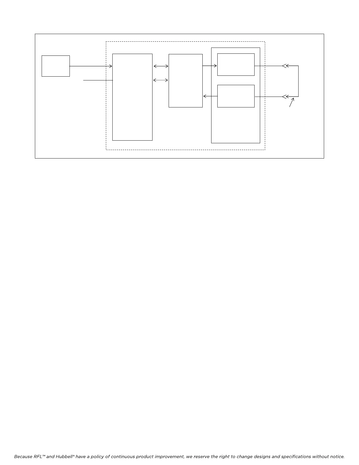
CH1
CH2
RS-232
BIT ERROR
TEST SET
MA-402I
MODULE
ADAPTER
IMUX 2000 TERMINAL MULTIPLEXER
RFL DA-91I
TRANSMIT
RECEIVE
COMMON
MODULE
DS1
EQUIP
OUT
DS1
EQUIP
IN
LOOP TEST
CABLE
Figure 4. Simplified block diagram, loop test for RFL DA-91I modules installed in terminal multiplexers.
9. Disconnect the patch cord from the DS1 EQUIP OUT and DS1 EQUIP IN jacks on the front of
the IMUX 2000, and close the front door.
If the above test procedure can be successfully completed, the RFL DA-91I module is functioning
properly. If not, use standard troubleshooting procedures to isolate the problem to the module itself, to
another module in the IMUX 2000, or to the T1 or E1channel. If the problem lies in the RFL DA-91I
module, replace it with a spare.
LOOP TEST PROCEDURE FOR RFL DA-91I MODULES
INSTALLED IN DROP/INSERT MULTIPLEXERS
The following procedure is used to test RFL DA-91I modules installed in IMUX 2000 drop/insert
multiplexers. To test DA-91I modules installed in IMUX 2000 terminal multiplexers, use the
procedure on page 15 of this instruction data sheet. Before performing this procedure, make sure the
system is on-line and out-of-service.
1. Open the door on the front of the IMUX 2000 multiplexer. Pull the DA-91I module out of the
shelf, and check the setting of DIP switch SW2-8.
For this part of the test, SW2-8 must be in the DOWN position to transmit on the
A bus and receive on the B bus.
2. Connect a patch cord between the DS1-A EQUIP OUT and DS1-B EQUIP IN jacks on the
front of the IMUX 2000 chassis. The jacks are located on the Common Module.
3. With power applied to the IMUX 2000, check the indicator(s) on the front of the power supply
module(s).
The POWER indicator(s) should be lit.
RFL DA-91I RFL Electronics Inc.
March 6, 2002 15 (973)
334-3100