Because RFL™ and Hubbell® have a policy of continuous product improvement, we reserve the right to change designs and specifications without notice.
1
2
3
4
5
6
7
8
9
10
11
12
13
14
15
16
17
18
19
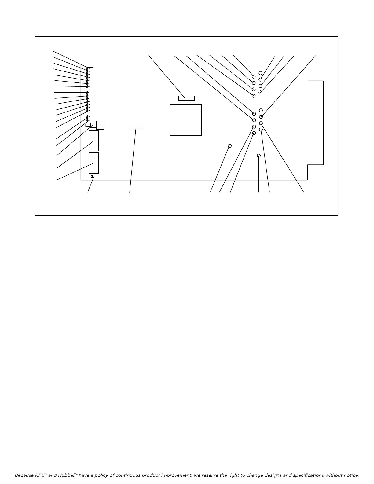
20 21 37 32 30 38 31 33
22 34 36 23 25 27 29 28 26 24 36
Figure 2. Controls and indicators, RFL DA-121I Asynchronous Data Channel Module
6. Select an unused time slot for channel 1 using DIP switches SW2-1 through SW2-5. Each
active voice channel uses one 64 Kbps digital time slot within the multiplexer’s aggregate rate.
Set the time slot using direct binary coding as shown in Table 3. Refer to the multiplexer
manual for guidelines on time slot selection.
Note that selecting an invalid time slot will disable the module. In T1 systems, only time slots 1
through 24 are allowed.
In E1 systems, time slots 1 through 31 are allowed, however, time slots 0 and 16 are reserved
and cannot be used.
7. Select transmit direction by using DIP switch SW2-8.
Place SW2-8 in the UP position to transmit in the B direction and receive from the
A direction. Place SW2-8 in the DOWN position to transmit in the A direction and
receive from the B direction. Unless otherwise specified at time of order, SW2-8 is
set in the DOWN position at the factory to transmit in the A direction, and receive
from the B direction.
>> text continues on page 9 <<
RFL DA-121I RFL El
ectronics Inc.
February 10, 2000 5 (973)
334-3100