Because RFL™ and Hubbell® have a policy of continuous product improvement, we reserve the right to change designs and specifications without notice.
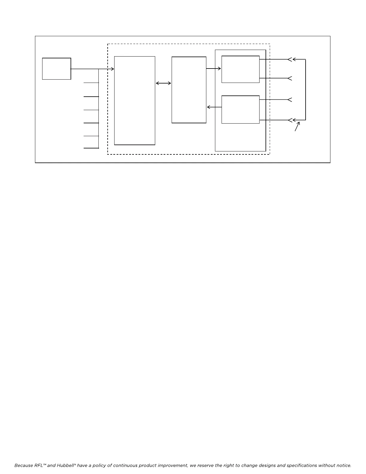
Figure 5. Simplified block diagram, loop test for RFL DA-121I modules installed in drop/insert multiplexers.
CABLE
ADAPTER
CH1
CH2
CH3
CH4
CH5
CH6
CH7
RS-232
BIT ERROR
TEST SET
MA-405I
MODULE
ADAPTER
IMUX 2000 DROP/INSERT MULTIPLEXER
RFL DA-121I
TRANSMIT
RECEIVE
COMMON
MODULE
DS1-A
EQUIP
OUT
DS1-B
EQUIP
OUT
DS1-A
EQUIP
IN
DS1-B
EQUIP
IN
PATCH
CORD
4. Check the CH1 Transmit and CH1 Receive activity LEDs on the front panel of the DA-121I
module. See Figure 2 and Table 1 for locations.
Both activity LEDs should NOT be lit.
5. Connect the BIT Error Test Set to the CH1 RS-232 connector on the cable assembly connected
to the Module Adapter for the RFL DA-121I module under test.
At this point, the equipment should be connected as shown in Figure 5.
6. At the test set, apply power and initialize the Request To Send (RTS) signal, and set its output
to any data rate up to 1.2 kbps. Check the CH1 Transmit and CH1 Receive activity LEDs on
the front of the RFL DS-121I.
Both activity LEDs should be ON.
7. Check the error count on the receive side of the test set.
The error count should be zero.
8. Repeat steps 3 through 7 with the test set connected to the other RS-232 connectors in the cable
assembly.
The results should be the same.
9. Disconnect the patch cord between the DS1-A EQUIP OUT and DS1-B EQUIP IN jacks on the
front of the IMUX 2000 chassis.
10. Pull the DA-121I module out of the shelf, and reset the setting of DIP switch SW2-8.
For this part of the test, SW2-8 must be in the OFF position to transmit on the B
bus and receive on the A bus.
11. Connect a patch cord between the DS1-B EQUIP OUT and DS1-A EQUIP IN jacks on the
front of the IMUX 2000 chassis. The jacks are located on the Common Module.
RFL DA-121I RFL Electronics Inc.
February 10, 2000 18 (973) 334-3100