Because RFL™ and Hubbell® have a policy of continuous product improvement, we reserve the right to change designs and specifications without notice.
The local loopback causes the data received from the local user equipment to be transmitted back to
the local user equipment un-molested. This is comparable to “wire” loopback since the data is not
buffered in any way. This loopback does NOT test the V.14 or V.110 circuits.
The remote loopback places the serial output receiver data (from the remote user equipment) into the
local transmitter path, and is ultimately transmitted back over the T1/E1 to the remote user equipment.
This loopback tests the transmit V.14 or V.110 circuits at BOTH the local and remote locations.
ALERTS/ALARMS
The DA-291B sends no Alert or Alarm signals to the shelf common card.
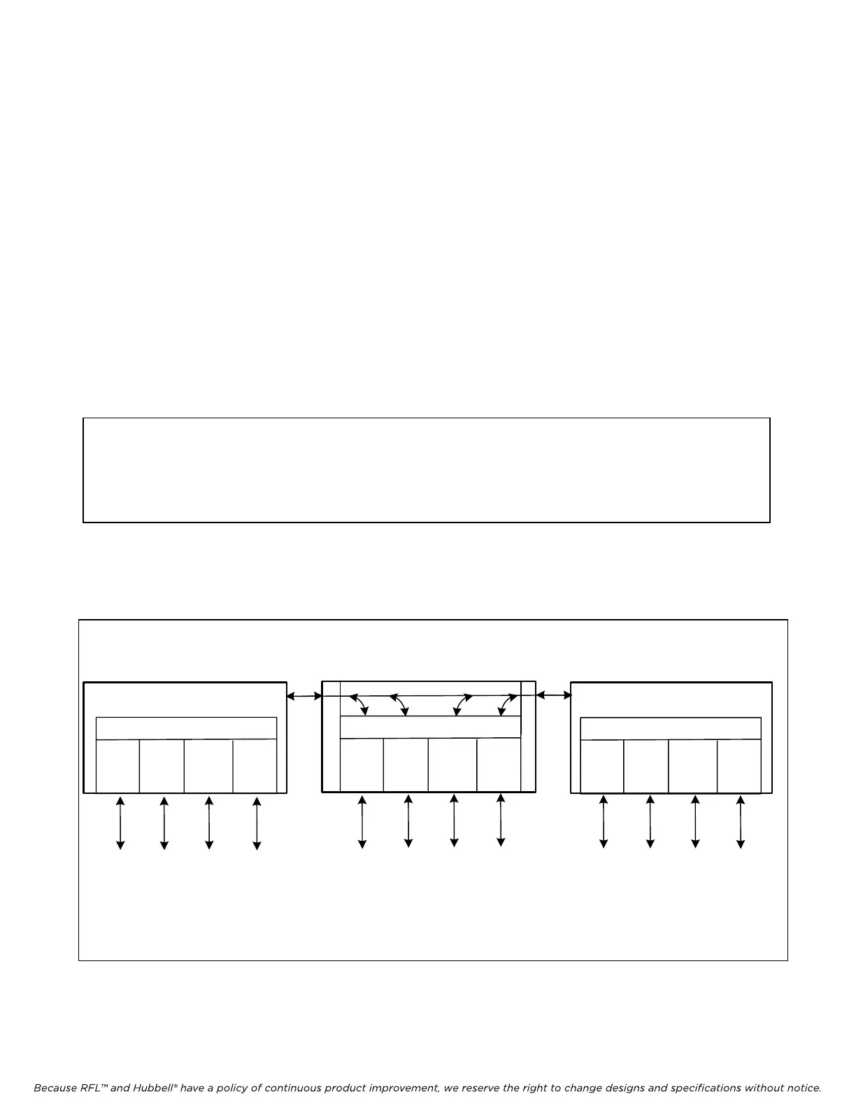
DROP AND INSERT OPERATION
A drop and insert multiplexer operates at a central point on a three (or more) node system. In the
example shown in Figure 4, Node 2 has a drop and insert multiplexer whose DI-A port is connected to
the transmission line to Node 1, and whose DI-B port is connected to the transmission line to Node 3.
Individual payload channels may connect Nodes 1 and 2, 1 and 3, or 2 and 3.
NOTE
In the drop and insert multiplexer at Node 2, a DA-291B module can set each individual
channel to transmit and receive either via the DI-A port (toward Node 1) or via the DI-B
port (toward Node 3), but not both.
When a DA-291B is installed in a terminal multiplexer (Node 1 or Node 3), each TERM switch must
be set UP. However, when it is installed in a drop and insert multiplexer (Node 2), set the TERM
switches UP to transmit and receive via the DI/A port (toward Node 1) and DOWN to transmit and
receive via the DI/B port (toward Node 3).
DA-291B
DA-291B
DA-291B
CH1
CH2
CH3 CH4
CH1 CH2
CH3
CH4 CH4CH3
CH2
CH1
DI/A
DI/B
T1/E1
T1/E1
To/from
node 2
CH 1
Term
Switch
UP
To/from
node 2
CH 2
Term
Switch
UP
To/from
node 3
CH 3
Term
Switch
UP
To/from
node 3
CH 4
Term
Switch
UP
To/from
node 1
CH 1
Term
Switch
UP
To/from
node 1
CH 2
Term
Switch
UP
To/from
node 3
CH 1
Term
Switch
DOWN
To/from
node 3
CH 2
Term
Switch
DOWN
To/from
node 2
CH 3
Term
Switch
UP
To/from
node 2
CH 4
Term
Switch
UP
To/from
node 1
CH 3
Term
Switch
UP
To/from
node 1
CH 4
Term
Switch
UP
Node 1
Terminal
Multiplexer
Node 2
Drop and Insert
Multiplexer
Node 3
Terminal
Multiplexer
Figure 4. Example of a Three-Node System Using Drop and Insert
RFL DA-291B RFL El
ectronics Inc.
April 13, 2010 18 (973)
334-3100