Because RFL™ and Hubbell® have a policy of continuous product improvement, we reserve the right to change designs and specifications without notice.
RFL VF-5A RFL Electronics Inc.
June 28, 2005 11 (973)
334-3100
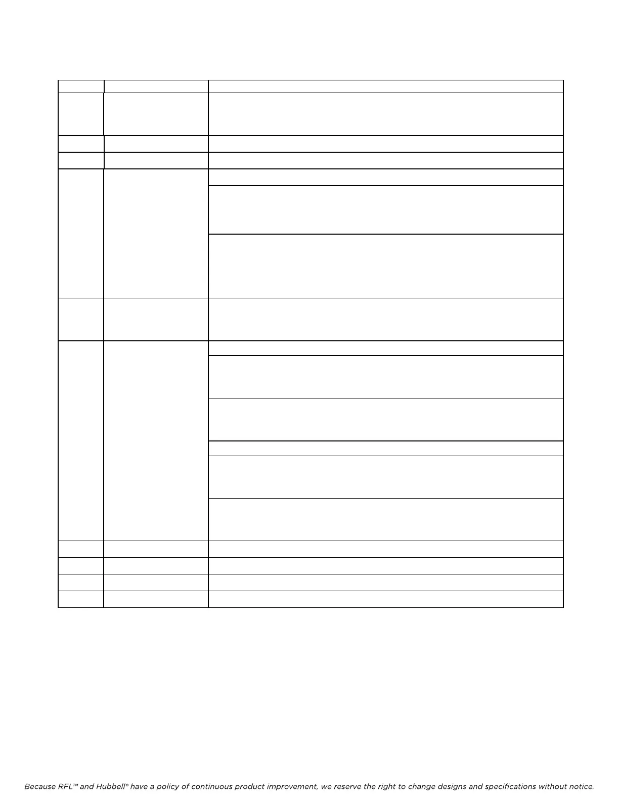
Table 1. Controls and indicators, RFL VF-5A Dual-Channel Four Wire E&M Voice Module - continued
Item Name/Description Function
5 Jumper E7 Controls Channel 2 E&M signaling types:
In Place (normal): Selects Type I signaling for Channel 2.
Rem
oved:
(1)
Selects Type II or Type III signaling for Channel 2.
6 DIP switch SW3 Sets Channel 2 transmit attenuator. Settings are the same as SW5 above
7 DIP switch SW2 Sets Channel 2 receive attenuator. Settings are the same as SW5 above
8 DIP switch SW1 SW1-1 to SW1-6 Select remote access address (See Table 2 on page 10 )
SW1-7
Enables local or remote control:
(2)
ON: Remote control is enabled.
OFF: Local control is enabled
SW1-8
Controls service:
ON: Service is off. If module is under local
control, module is disabled.
OFF: Service is on. If module is under local
control, module is enabled.
9 Jumper E5 Controls Channel 2 operation:
In place:
Channel 2 off for one-channel operation.
Removed (normal):
(1)
Channel 2 active for two-channel operation.
10 DIP switch SW6 SW6-1 to SW6-5 Selects time slots using codes shown in table 3.
SW6-6
Transmit Bus Selection:
(3)
UP: Module will transmit on B, receive on A.
DOWN: Module will receive on B, transmit on A.
SW6-7
Controls E&M signaling (per AT&T Publication 43801):
(4)
UP: E&M signaling enabled.
DOWN: E&M signaling disabled.
SW6-8 Not used.
SW6-9 Controls BUSY 1 output:
UP: Normal operation.
DOWN: BUSY OUT (OFF HOOK) on Channel 1.
SW6-10 Controls BUSY 2 output:
UP: Normal operation.
DOWN: BUSY OUT (OFF HOOK) on Channel 2.
11 E2 indicator (green) Lights when signaling is turned on and E2 lead is active.
12 M2 indicator (green) Lights when M2 lead is active.
13 E1 indicator (green) Lights when signaling is turned on and E1 lead is active
14 M1 indicator (green) Lights when M1 lead is active.
1. When removing jumpers, attach them to one of the pins so that they are available for future use.
2. When the module is set for remote control (SW1-7 in ON position), SW1-8 is not used.
3. If the RFL VF-5A is being installed in a term
inal multiplexer, this switch should always be OFF. If the RFL VF-
5A
is being installed in a drop/insert multiplexer, set this switch OFF to communicate via the DI-A common
module; set it ON to communicate via the DI-B common module.
4. When signaling is turned on, the logic circuitry robs one bit from the transmission every sixth frame of the frame
format
to use for signaling. If signaling is OFF, it uses all bits for voice encoding. Signaling should be off when using
a voice-grade data modem over a voice-frequency circuit.