Because RFL™ and Hubbell® have a policy of continuous product improvement, we reserve the right to change designs and specifications without notice.
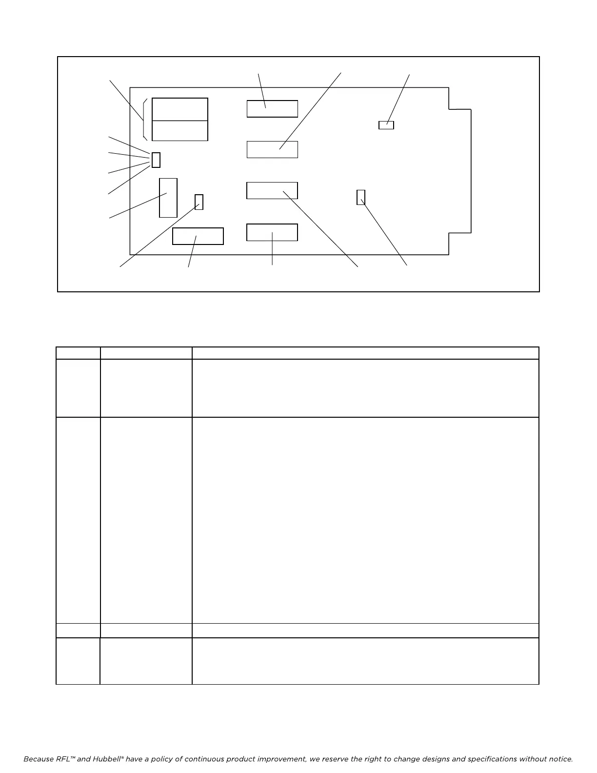
3
1
2
4
5
7
6
9
10
14
13
12
11
8
Figure 7. Controls and indicators, RFL VF-5A Dual-Channel Four Wire E&M Voice Module
Table 1. Controls and indicators, RFL VF-5A Dual-Channel Four Wire E&M Voice Module
Item Name/Description Function
1 Equipment jacks Allow channel signals to be equipped:
CH1 IN Equipment point for Channel 1 input signal
CH1 OUT
Equipment point for Channel 1 output signal
CH2 IN Equipment point for Channel 2 input signal
CH2 OUT
Equipment point for Channel 2 output signal
2 DIP switch SW5 Sets Channel 1 transmit attenuator:
SW5-1 0.1 dB
SW5-2 0.2 dB
SW5-3 0.4 dB
SW5-4 0.8 dB
SW5-5 1.5 dB
SW5-6 3.0 dB
SW5-7 6.0 dB
SW5-8 12.0 dB
Switch settings are cumulative. For example, to set the attenuation to 19.0 dB,
turn on SW5-2, SW5-4, SW5-7, and SW5-8; to set attenuation to 7.6 dB,
turn on SW5-1, SW5-5, and SW5-7.
The values shown above allow any setting from
zero (no attenuation) to 24 dB,
in
0.1 dB increments. Set at the factory for 3 dB. (See Page 18 for more
information)
3 DIP switch SW4 Sets Channel 1 receive attenuator. Settings are the same as SW5 above.
4 Jumper E6 Controls Channel 1 E&M signaling types:
In Place (normal): Selects Type I signaling for Channel 1.
Removed:
(1)
Selects Type II or Type III signaling for Channel 1.
RFL VF-5A RFL Electronics Inc.
June 28, 2005 10 (973)
334-3100