Because RFL™ and Hubbell® have a policy of continuous product improvement, we reserve the right to change designs and specifications without notice.
RFL VF-5A RFL Electronics Inc.
June 28, 2005 14 (973)
334-3100
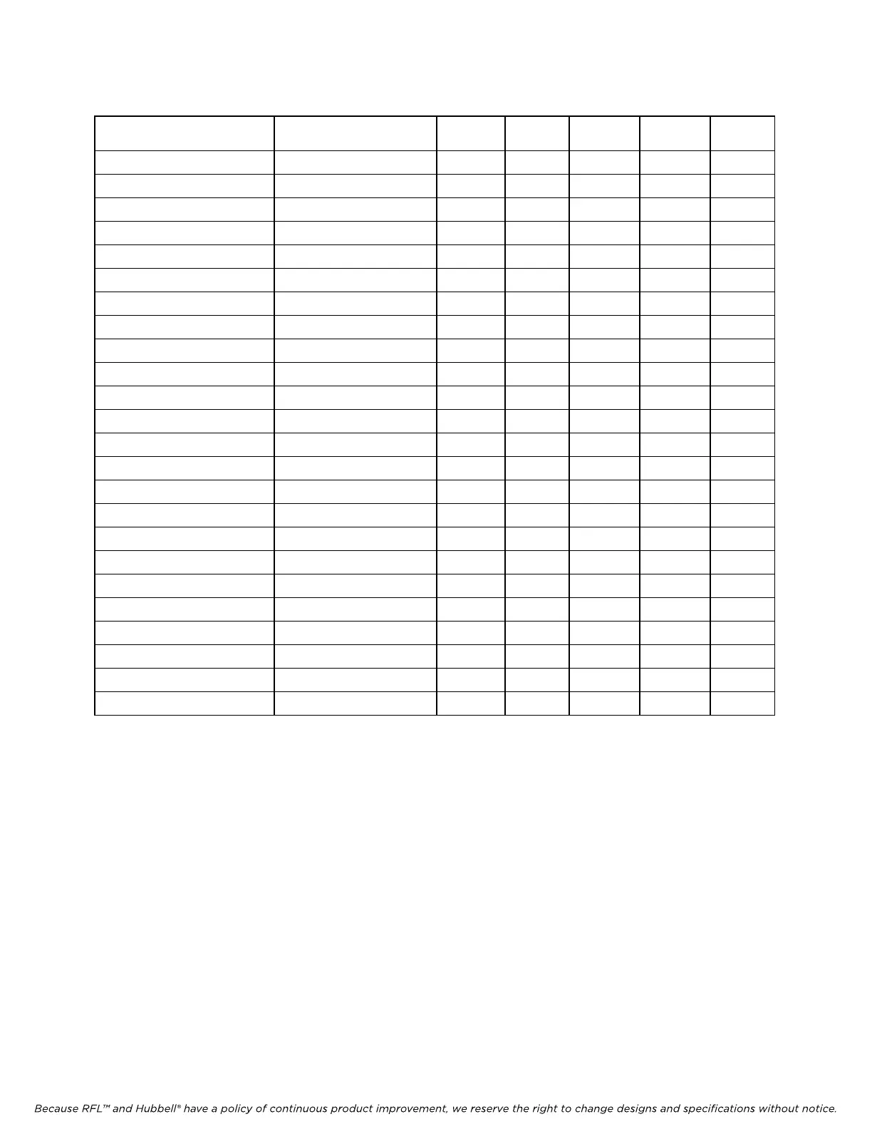
Table 3. Time slot selection, RFL VF-5A Dual-Channel Four Wire E&M Voice Module
One-Channel Operation
(Jumper E5 in place)
Two-C
hannel Operation
(Jumper E5 removed)
SW6-1 SW6-2 SW6-3 SW6-4 SW6-5
1 1 and 2 UP UP UP UP UP
2 2 and 3 UP UP UP UP DOWN
3 3 and 4 UP UP UP DOWN UP
4 4 and 5 UP UP UP DOWN DOWN
5 5 and 6 UP UP DOWN UP UP
6 6 and 7 UP UP DOWN UP DOWN
7 7 and 8 UP UP DOWN DOWN UP
8 8 and 9 UP UP DOWN DOWN DOWN
9 9 and 10 UP DOWN UP UP UP
10 10 and 11 UP DOWN UP UP DOWN
11 11 and 12 UP DOWN UP DOWN UP
12 12 and 13 UP DOWN UP DOWN DOWN
13 13 and 14 UP DOWN DOWN UP UP
14 14 and 15 UP DOWN DOWN UP DOWN
15 15 and 16 UP DOWN DOWN DOWN UP
16 16 and 17 UP DOWN DOWN DOWN DOWN
17 17 and 18 DOWN UP UP UP UP
18 18 and 19 DOWN UP UP UP DOWN
19 19 and 20 DOWN UP UP DOWN UP
20 20 and 21 DOWN UP UP DOWN DOWN
21 21 and 22 DOWN UP DOWN UP UP
22 22 and 23 DOWN UP DOWN UP DOWN
23 23 and 24 DOWN UP DOWN DOWN UP
24 . . . DOWN UP DOWN DOWN DOWN
NOTE: Each active time slot on an RFL VF-5A module occupies one 64-Kbps digital time slot within the multiplexer's
aggregate rate. Consult the IMUX 2000 instruction manual for guidelines on time slot selection.
21. Set DIP switch SW6-10 to control the BUSY 1 output.
Place SW6-10 in the ON position for normal operation. To enable BUSY OUT
(OFF-HOOK) on Channel 2, place SW6-10 in the OFF position.
22. Slide the RFL VF-5A module into the selected module slot until it is firmly seated and the
module front panel is flush with the top and bottom of the shelf.
23. On the Module Record Card (located to the right of the shelf) record the channel bank type,
time slot, and any other pertinent information.
The RFL VF-5A module is now installed.