Because RFL™ and Hubbell® have a policy of continuous product improvement, we reserve the right to change designs and specifications without notice.
RFL VF-5C RFL Electronics Inc.
October 8, 2012 18 (973) 334-3100
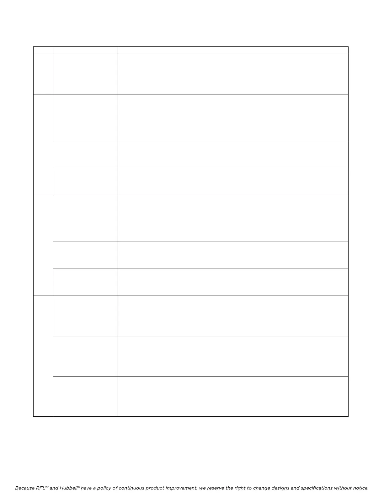
Table 1. Controls and indicators, RFL VF-5C module
Item Name/Description Function
1
Equipment jacks Allow channel signals to be equipped:
CH1 IN Equipment point for Channel 1 input signal.
CH1 OUT Equipment point for Channel 1 output signal.
CH2 IN Equipment point for Channel 2 input signal.
CH2 OUT Equipment point for Channel 2 output signal.
2 DS1 LED Channel 1 Addressing LED (has three states)
Off: Addressing feature is turned OFF.
Green: Addressing feature is turned ON and the module is receiving the
correct address from the far end
Red: Addressing feature is turned ON and the module is not receiving
the correct address from the far end. This condition causes muting of CH1 OUT.
DS2 LED Channel 1 “E-Lead” LED (has two states)
Off: Signaling is OFF or signaling is ON and “E-Lead” output is inactive.
Green: Signaling is ON and “E-Lead” output is active.
DS3 LED Channel 1 “M-Lead” LED (has two states)
Off: Signaling is OFF or signaling is ON and “M-Lead” input is inactive.
Green: Signaling is ON and “M-Lead” input is active.
3 DS4 LED Channel 2 Addressing LED (has three states)
Off: Addressing feature is turned OFF.
Green: Addressing feature is turned ON and the module is receiving the
correct address from the far end
Red: Addressing feature is turned ON and the module is not receiving
the correct address from the far end. This condition causes muting of CH2 OUT.
DS5 LED Channel 2 “E-Lead” LED (has two states)
Off: Signaling is OFF or signaling is ON and “E-Lead” output is inactive.
Green: Signaling is ON and “E-Lead” output is active.
DS6 LED Channel 2 “M-Lead” LED (has two states)
Off: Signaling is OFF or signaling is ON and “M-Lead” input is inactive.
Green: Signaling is ON and “M-Lead” input is active.
4 DS7 LED Channel 1 Loopback LED (has four states)
Off: No loopbacks are active
Red: Remote loopback is active
Green: Local loopback is active
Flashing Red: Remote loopback is active and was activated by 2713 Hz from Master end.
DS8 LED Channel 2 Loopback LED (has four states)
Off: No loopbacks are active
Red: Remote loopback is active
Green: Local loopback is active
Flashing Red: Remote loopback is active and was activated by 2713 Hz from Master end.
DS9 LED Service On/Off LED (has four states)
Off: Service is OFF.
Green: Service is ON and module configuration is valid.
Red: Service is OFF due to CH1 and CH2 being set to same timeslot and bus direction.
Amber: Service is ON but either CH1 or CH2 is set to an invalid timeslot.