Because RFL™ and Hubbell® have a policy of continuous product improvement, we reserve the right to change designs and specifications without notice.
RFL VF-5C RFL Electronics Inc.
October 8, 2012 19 (973)
334-3100
Table 1. continued - Controls and indicators, VF-5C module
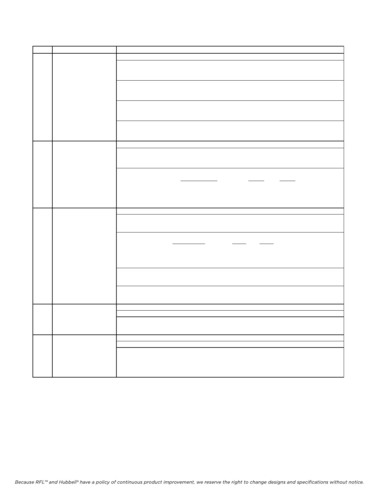
Item Name/Description Function
5 DIP Switch SW1 SW1-1 to SW1-6 Selects SCB address in accordance with Table 2.
SW1-7: Enables or disables Channel 1
ON: Channel 1 disabled
OFF: Channel 1 enabled
SW1-8: Enables or disables Channel 2
ON: Channel 2 disabled
OFF: Channel 2 enabled
SW1-9: Selects automatic or manual deactivation of 2713 Hz loopback for Channel 1
ON: Selects automatic mode
OFF: Selects manual mode
SW1-10 Selects automatic or manual deactivation of 2713 Hz loopback for Channel 2
ON: Selects automatic mode
OFF: Selects manual mode
6 DIP Switch SW2 SW2-1 to SW2-5 Selects Channel 1 timeslot in accordance with Table 3.
SW2-6 Selects Channel 1 bus direction as follows:
DOWN: Terminal or DI-A (Transmits in A direction, receives from B direction)
UP: DI-B (Transmits in B direction, receives from A direction)
SW2-7 & SW2-8 Selects Channel 1 Loopback Mode as follows:
Loopback Mode
SW2-7 SW2-8
None OFF OFF
Local OFF ON
Remote ON OFF
2713 Hz induced loopback (1) ON ON
7 DIP Switch SW3 SW3-1 to SW3-5 Selects Channel 2 timeslot in accordance with Table 3.
SW3-6 Selects Channel 2 bus direction as follows:
DOWN: Terminal or DI-A (Transmits in A direction, receives from B direction)
UP: DI-B (Transmits in B direction, receives from A direction)
SW3-7 & SW3-8 Selects Channel 2 Loopback Mode as follows:
Loopback Mode
SW3-7 SW3-8
None OFF OFF
Lo
cal OFF ON
Remote ON
OFF
2713 Hz induced loopback (1
) ON ON
SW3-9 Selects remote or local mode as follows:
DOWN: Remote mode
UP: Local mode
SW3-10 Selects service ON or OFF as follows:
DOWN: Service OFF
UP: Service ON
8 DIP Switch SW4 SW4-1 Selects polarity (+ or -) of Channel 1 Tx level
(CH1 TX LVL) SW4-2 to SW4-7 Selects magnitude of Channel 1 Tx level (See Note 2)
SW4-8 Enables or disables Channel 1signaling as follows:
ON: Signaling enabled
OFF Signaling disabled
9 DIP Switch SW5 SW5-1 Selects polarity (+ or -) of Channel 1 Rx level
(CH1 RX LVL) SW5-2 to SW5-7 Selects magnitude of Channel 1 Rx level (See Note 2)
SW5-8 Activates or deactivates the Channel 1 Busy Function. Identical in function to the
trunk circuit activating the M lead. Use this switch to force the off-hook condition as
follows:
ON: Busy (Off-Hook equivalent)
OFF Normal (Follows actual ON/Off-Hook input)
Notes:
1. When SW2-7 and SW2-8 are both down, the 2713Hz loopback function is enabled. Then set SW1-9 and SW1-10 as
required.
2. Th
e v
alue of these switches is additive, see the examples in steps 13 and 14 of Installation Instructions. The factory
default setting is –16dBm in and +7dBm
out. (See Tables 4 and 5 for Tx and Rx Level Settings)