Because RFL™ and Hubbell® have a policy of continuous product improvement, we reserve the right to change designs and specifications without notice.
Table 1. continued - Controls and indicators, VF-5C module
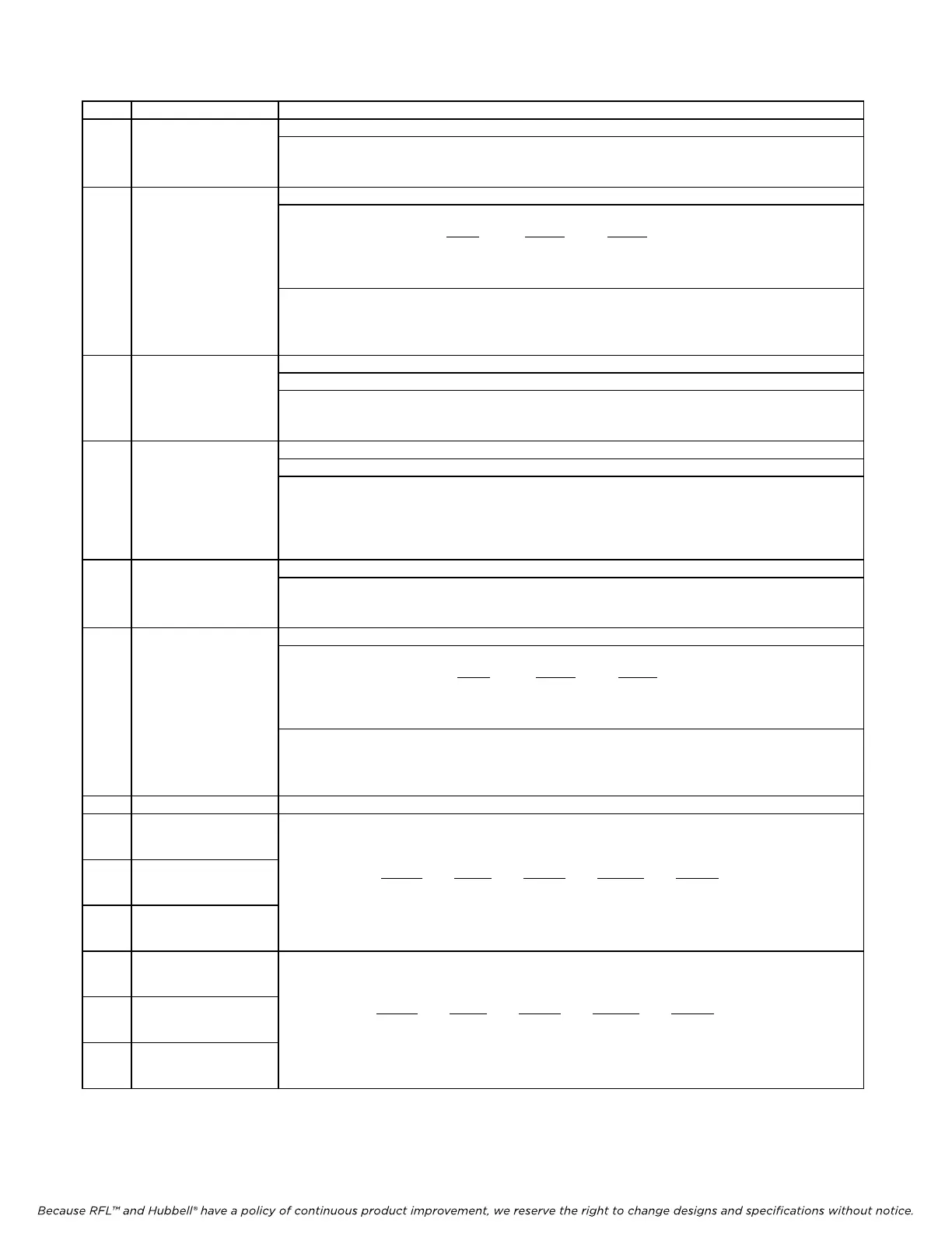
Item Name/Description Function
10 DIP Switch SW6 SW6-1 to SW6-7 Selects Channel 1 Tx address
(CH1 TX ADDR) SW6-8 Enables or disables Channel 1 addressing as follows:
ON: Channel 1 addressing enabled
OFF Channel 1 addressing disabled
11 DIP Switch SW7 SW7-1 to SW7-7 Selects Channel 1 Rx address
(CH1 RX ADDR) SW7-8 & SW7-9 Enables or disables FXS/FXO modes for Channel 1 as follows:
Mode
SW7-8 SW7-9
Normal mode OFF ON or OFF
FXS mode ON ON
FXO mode ON OFF
SW7-10 Activates or deactivates 1kHz, 0dBm0 test tone (G.711 digital mW), in Tx path for
Channel 1 as follows:
ON: Test tone ON
OFF Test tone OFF
12 DIP Switch SW8 SW8-1 Selects polarity (+ or -) of Channel 2 Tx level
(CH2 TX LVL) SW8-2 to SW8-7 Selects magnitude of Channel 2 Tx level (See note 2 on page 19)
SW8-8 Enables or disables Channel 2 signaling as follows:
ON: Signaling enabled
OFF Signaling disabled
13 DIP Switch SW9 SW9-1 Selects polarity (+ or -) of Channel 2 Rx level
(CH2 RX LVL) SW9-2 to SW9-7 Selects magnitude of Channel 2 Rx level (See note 2 on page 19)
SW9-8 Activates or deactivates the Channel 2 Busy Function. Identical in function to the
trunk circuit activating the M lead. Use this switch to force the off-hook condition as
follows:
ON: Busy (Off-Hook)
OFF Not busy (On-Hook)
14 DIP Switch SW10 SW10-1 to SW10-7 Selects Channel 2 Tx address
(CH2 TX ADDR) SW10-8 Enables or disables Channel 2 addressing as follows:
ON: Channel 2 addressing enabled
OFF Channel 2 addressing disabled
15 DIP Switch SW11 SW11-1 to SW11-7 Selects Channel 2 Rx address
(CH2 RX ADDR) SW11-8 & SW11-9 Enables or disables FXS/FXO modes for Channel 2 as follows:
Mode
SW11-8 SW11-9
Normal mode OFF ON or OFF
FXS mode ON ON
FXO mode ON OFF
SW11-10 Activates or deactivates 1kHz, 0dBm0 test tone(G.711 digital mW), in Tx path for
Channel 2 as follows:
ON: Test tone ON
OFF Test tone OFF
16 J1 Programming header (for factory use only)
17
J7 Jumper
18
J8 Jumper
19
J11 Jumper
20
J9 Jumper
21
J10 Jumper
22
J12 Jumper
Jumpers J7, J8 and J11 are used to set the Channel 1 E&M Signaling Type as follows:
Channel 1 Signaling Type
Jumper
Type I Type II Type III Type V
J7 B B B A
J8 B B B A
J11 B A B B
Jumpers J9, J10 and J12 are used to set the Channel 2 E&M Signaling Ty
pe as follows:
Channel 2 Signaling Ty
pe
Jumper
Type I Type II Type III Type V
J9 B B B A
J10 B B B A
J12 B A B B
RFL VF-5C RFL Electronics Inc.
October 8, 2012 20 (973)
334-3100