Because RFL™ and Hubbell® have a policy of continuous product improvement, we reserve the right to change designs and specifications without notice.
16
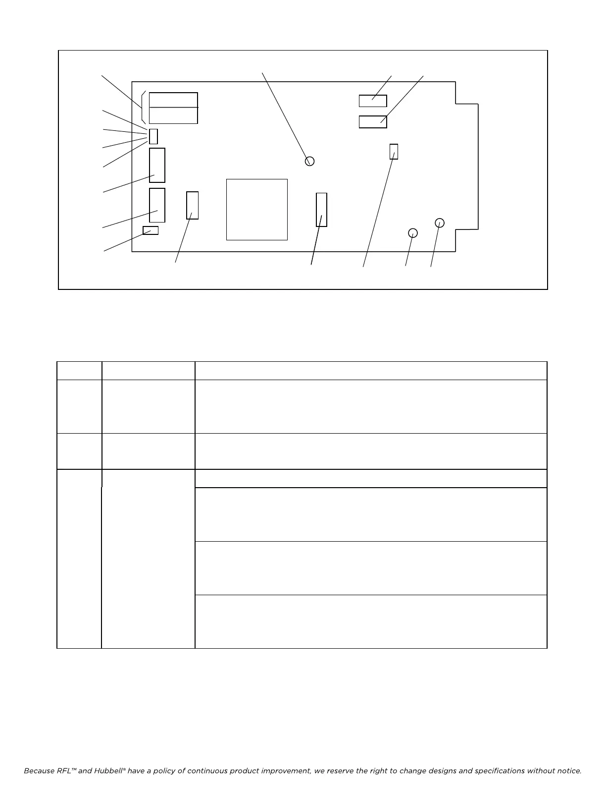
6
1
13
14
11
4
3
2 12
15
9
10
8
7
5
Figure 6. Controls and indicators, RFL VF-6I Four Wire Orderwire Voice Frequency Module
Table 1. Controls and indicators, RFL VF-6I Four Wire Orderwire Voice Frequency Module
Item Name/Description Function
1 Equipment jacks Allow channel signals to be equipped:
IN Equipment point for input signal
OUT
Equipment point for output signal
2 DIP switch SW1 SW1-1 to SW1-6 Selects the remote address (SCB address) using the codes
shown in Table 2.
3 DIP switch SW2 SW2-1 to SW2-5 Selects time slots using codes shown in Table 3.
SW2-6
(3)
Bus A Selection:
DOWN: Bus A enabled (TXA/RXB)
UP: Bus A disabled
SW2-7
(3)
Bus B Selection:
DOWN: Bus B enabled (TXB/RXA)
UP: Bus B disabled
SW2-8 Selects T1 or E1
UP: Selects T1 operation
DOWN: Selects E1 operation.
RFL VF-6I RFL Electronics Inc.
December 15, 2011 10 (973) 334-3100