Because RFL™ and Hubbell® have a policy of continuous product improvement, we reserve the right to change designs and specifications without notice.
RFL VF-6I RFL Electronics Inc.
December 15, 2011 11 (973)
334-3100
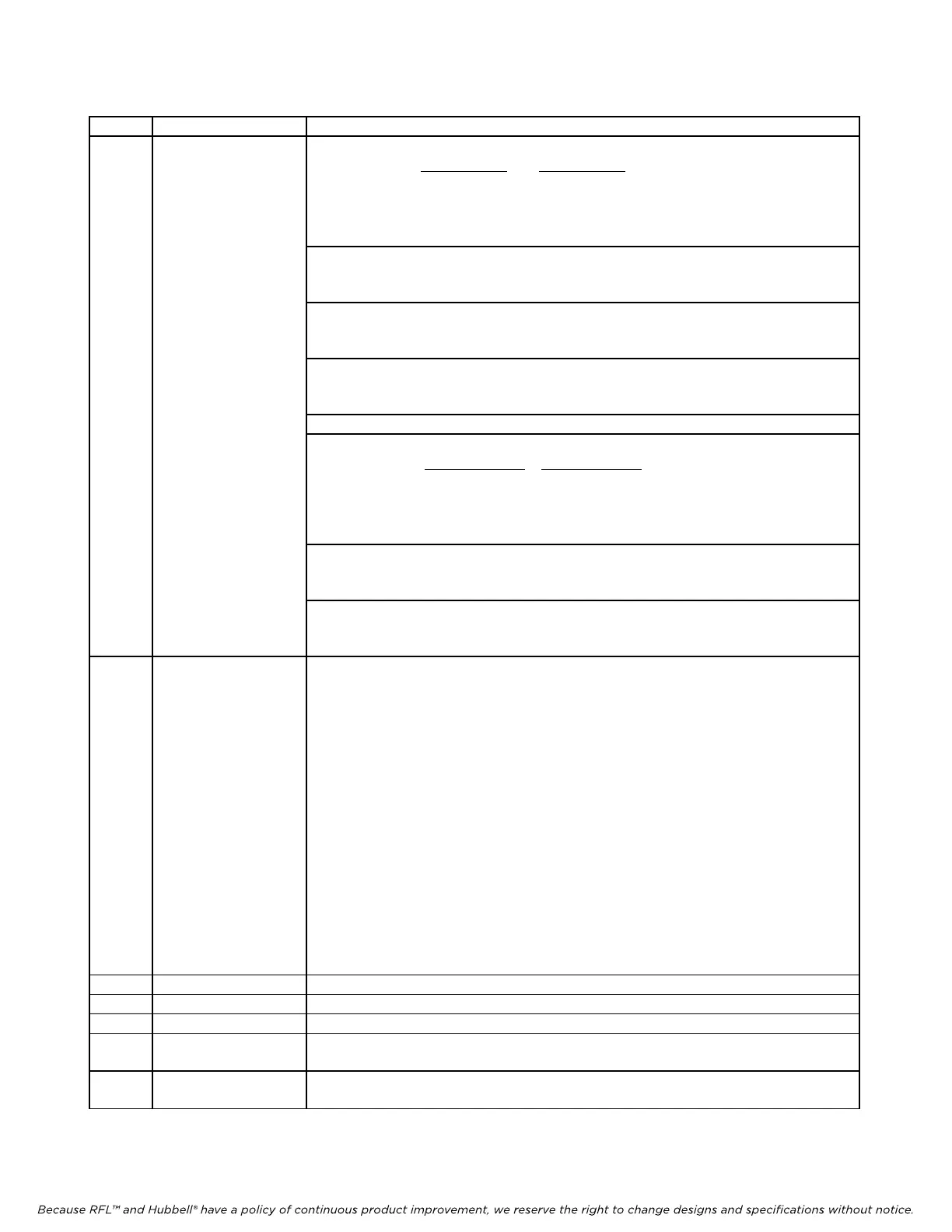
Table 1. Controls and indicators, RFL VF-6I Four Wire Orderwire Voice Frequency Module - continued
Item Name/Description Function
4 DIP switch SW3 SW3-1 & SW3-2 Transmit control modes
TC1 (SW
3-1)
TC0 (SW3-2)
DOWN DOWN Continuous mode
DOWN UP Hook Switch mode
UP DOWN Voice activate (VOX) mode
UP UP
Receive only mode
SW3-3 Signaling control
(4)
UP: Enables CAS for E1 or Enables RBS for T1
DOWN: Disables signaling
SW3-4 Busy control
UP: Normal
DOWN: Busy out
SW3-5 Bridge mode/Multi-drop mode
UP (OFF): Bridge mode
DOWN (ON):
Multi-drop mode (orderwire mode)
SW3-6 Spare
SW3-7 & SW3-8 Sets threshold for voice activate mode.
VOX1 (SW
3-7)
VOX0 (SW3-8)
DOWN DOWN (minimum threshold)
DOWN UP
UP DOWN
UP
UP (maximum threshold)
SW3-9 Remo
te/local control
(2)
UP: Local operation
DOWN: Remote operation
SW3-10 Service ON/OFF control
UP: Service ON
DOWN: Service OFF
5 DIP switch SW4 Sets receive attenuator:
SW4-1 0.1 dB
SW4-2 0.2 dB
SW4-3 0.4 dB
SW4-4 0.8 dB
SW4-5 1.5 dB
SW4-6 3.0 dB
SW4-7 6.0 dB
SW4-8 12.0 dB
Switch settings are cumulative. For example, to set the attenuation to 19.0 dB,
turn on SW4-2, SW4-4, SW4-7, and SW4-8; to set attenuation to 7.6 dB,
turn on SW4-1, SW4-5, and SW4-7.
The values shown above allow any setting from zero (no attenuation) to 24 dB,
in 0.1 dB increments. Set at the factory for 3 dB
. (See Table 4 for a list of
attenuation calibration settings)
6 DIP switch SW5 Sets transmit attenuator. Settings are the same as SW4 above
7 M indicator (green) Lights when M lead is active or signaling control input is active.
8 E indicator (green) Lights when signaling is turned on and E lead is active
9 TX activity indicator
(green)
Lights when data is transmitted to remote equipment
10 RX activity indicator
(green)
Lights when data is received from remote equipment