Because RFL™ and Hubbell® have a policy of continuous product improvement, we reserve the right to change designs and specifications without notice.
RFL VF-6I RFL Electronics Inc.
December 15, 2011 12 (973) 334-3100
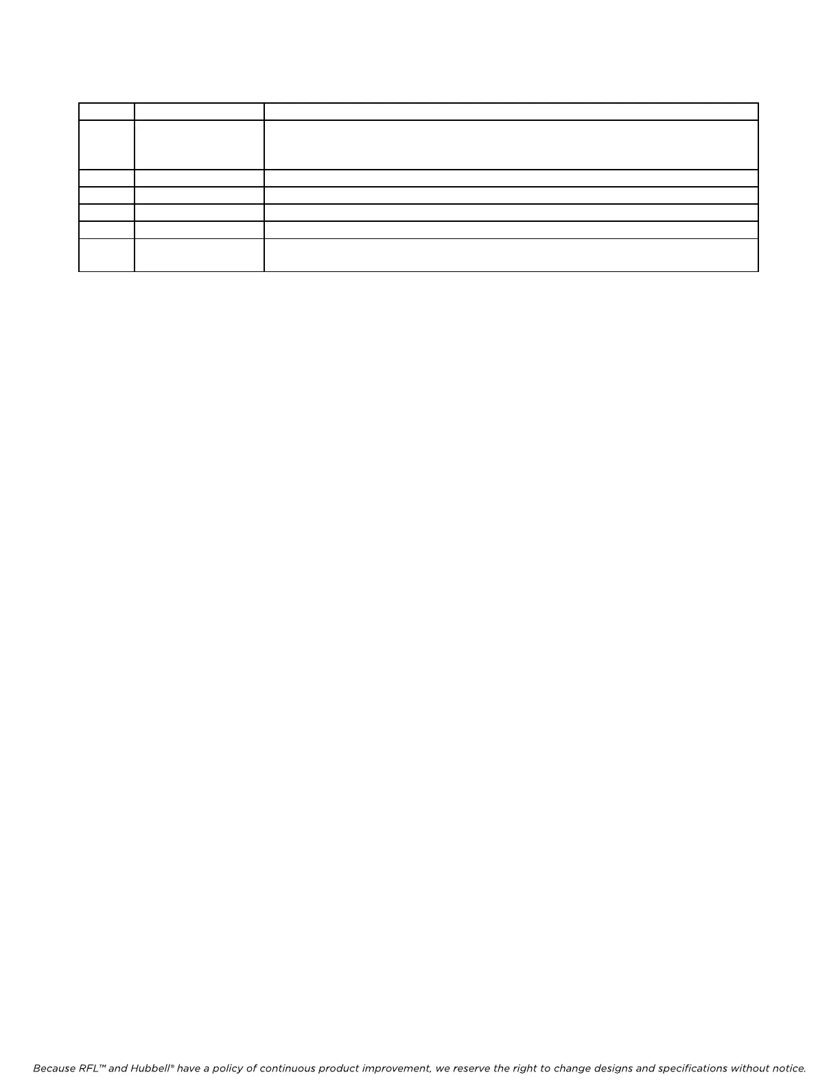
Table 1. Controls and indicators, RFL VF-6I Four Wire Orderwire Voice Frequency Module - continued
Item Name/Description Function
11
Jumper J1
(1)
Controls signaling type:
In Place (normal):
Selects Type I signaling.
Removed: Selects Type II or Ty
pe III signaling.
12 J3 For factory use only
13 Test point TP1 For factory use only
14 Test point TP2 For factory use only
15 Test point TP3 For factory use only
16 Service indicator
(green)
Lights when module is in service.
1. When removing jumpers, attach them to one of the pins so that they are available for future use.
2. When the module is set for remote control (SW
3
-9 in DOWN position), SW3-10 is not used.
3. If the RFL VF-6I is being installed in a terminal multiplexer, set SW2-6 (DOWN) and SW2-7 (UP). If the RFL
VF-6I is being installed in a drop/insert multiplexer, set SW2-6 (DOWN) to communicate via the DI-A common
m
odule and set SW2-7 (DOWN) to communicate via the DI-B common module.
4. If the card is set for E1 operation and signaling is enabled (CAS), the signaling bits are sent in time slot 16, per CCITT
Recomm
endation G.704. The multiplexer must also be set to use CAS signaling.
5. If card is set for T1 operation and signaling is enabled (ROBBED BIT) the logic circuitry robs one bit from the PCM-
encoded voice transm
ission every eighth frame and replaces it with a signaling bit.