Because RFL™ and Hubbell® have a policy of continuous product improvement, we reserve the right to change designs and specifications without notice.
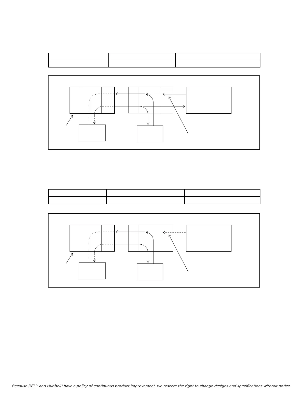
2. VF6I operating with an RTU.
a. The VF-6I transmits local data in one bus direction, toward the Master (MTU),
and passes received data in the same bus direction
BUS A OR BUS B ENABLED SW2-6 or SW2-7 DOWN (ON)
BRIDGE MODE ENABLED SW3-5 UP (OFF)
TERMINAL OR D&I D&I TERMINAL OR D&I
VF6I VF6I
BUS A BUS B
RTU
MTU
RECEIVED CHANNEL DATA
IS PASSED THRU
MASTER
NODE
Figure 9. VF6I configured for RTU operation in one bus direction (Bus A enabled) in the middle of a
chain of RTUs
b. The VF-6I transmits local data from the Terminal end (or D&I end) toward the Master
(MTU). The VF6I does not pass received data thru.
BUS A OR BUS B ENABLED SW2-6 or SW2-7 DOWN (ON)
MULTI-DROP MODE MULTI-DROP MODE ENABLED SW3-5 DOWN (ON)
TERMINAL OR D&I D&I TERMINAL OR D&I
VF6I VF6I
BUS A BUS B
RTU
MTU
RECEIVED CHANNEL DATA
DOES NOT PASS THRU
MASTER
NODE
Figure 10. VF6I configured for RTU operation in one bus direction (Bus A enabled) at the end of a
chain of RTUs
RFL VF-6I RFL Electronics Inc.
Decem
ber 15, 2011 17 (973) 334-3100