Because RFL™ and Hubbell® have a policy of continuous product improvement, we reserve the right to change designs and specifications without notice.
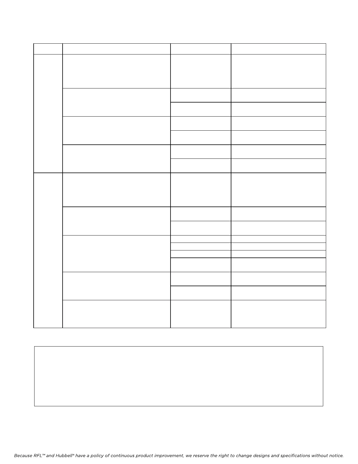
Table 5. Remote configuration settings (“P” codes)
P Code Digit(s) and Switch Equivalent Value Description
P1
B00000000
↑↑↑↑↑
TIME SLOT SELECT
00001 to 11111 for E1
00001 to 11000 for T1
From left to right, these five bits
represent t
he binary value of the
desired time slot. See Table 7 for a
complete list of these values.
B00000000
↑
0 Selects T1 system
SYSTEM TYPE
1 Selects E1 system
B00000000
↑
0 Bus B disabled
BUS B
1 Bus B enabled
B00000000
↑
0 Bus A disabled
BUS A
1 Bus A enabled
P2
B00000000
↑↑
VOICE ACTIVATE SETTINGS (VOX
)
00 to 11 Selects level of voice activate setting.
00 = minimum setting
11 = maximum setting
B00000000
↑
0 Signaling enabl
e
d
CAS for E1, RBS for T1
SIGNALING
1 Signaling disabled
B00000000
00 Receive only
↑↑
01 Voice activate (VOX)
10 Hook-switch
TRANSMIT CONTROL MODES
11 Continuous
B00000000
↑
0 Bridge m
ode
MODE
1 Multi-drop mo
de
B00000000
↑
↑
SPARE
... Not currently used
NOTE
When using binary numbers with a SET command, they must be preceeded by the letter “B”
as shown in the following example:
<MULTIPLEXER ADDRESS>:<CARD ADDRESS>:SET:P1 = B00000011;
RFL VF-6I RFL Electronics Inc.
December 15, 2011 24 (973) 334-3100