Because RFL™ and Hubbell® have a policy of continuous product improvement, we reserve the right to change designs and specifications without notice.
MA-306
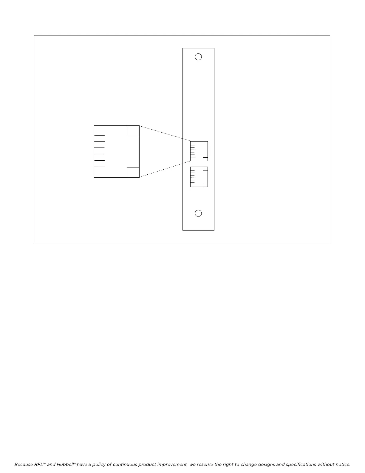
1
2
3 RING
4 TIP
5
6
PIN 3 = RING
PIN 4 = TIP
PINS 1, 2, 5, 6 NOT USED
LOCAL PHONE (RJ-11 JACK)
FOR FUTURE USE
FXS
FXO
Figure 1. MA-306 Module Adapter.
6. Set the module SCB address using DIP switches SW1-1 through SW1-6.
For remote access, each channel module in the IMUX 2000 must have a distinct
module address. Valid addresses are the numbers “1” to “36”. In most
installations the address will be set to the number of the slot the module is
occupying. Table 2 shows the switch settings for the module address. (Consult
your multiplexer manual for details on using the remote access and configuration
features of the system.)
7. Select an unused time slot using DIP switches SW2-1 to SW2-5. The voice channel uses one 64
kbps digital time slot within the multiplexer’s aggregate rate. Set the time slot using direct
binary coding as shown in Table 3. Refer to the multiplexer manual for guidelines on time slot
selection.
Note that selecting an invalid time slot will disable the module. In T1 systems, only time slots 1
through 24 are allowed. Time slot 24 is not available for a T1 system using fast reframing.
In E1 systems, time slots 1 through 31 are allowed, however, time slots 0 and 16 are reserved
and cannot be used. Time slot 30 is not available for an E1 system using fast reframing. Time
slot 31 is not available if inter-node communications (NMX) is used.
RFL VF-8A RFL Electronics Inc.
August 6, 2010 5 (973)
334-3100