Because RFL™ and Hubbell® have a policy of continuous product improvement, we reserve the right to change designs and specifications without notice.
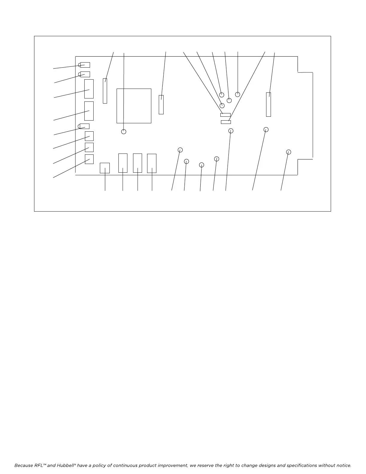
16 24 17 14 27 29 25 26 15 13
6 10 11 12 28 22 20 21 23 19 18
1
2
4
5
3
7
8
9
Figure 2. Controls and indicators, RFL VF-8A Selective Calling Unit
8. Set DIP switch SW2-6 to enable or disable Bus A.
Place SW2-6 in the DOWN position to transmit on Bus A and receive on Bus B.
Place SW2-6 in the UP position to disable Bus A.
9. Set DIP switch SW2-7 to enable or disable Bus B.
Place SW2-7 in the DOWN position to transmit on Bus B and receive on Bus A.
Place SW2-7 in the UP position to disable Bus B.
10. The 16-position rotary DIP switch SW3 is used to select the desired number of ring attempts.
Place SW3 to the desired setting in accordance with Table 4.
<< te
xt continues on page 10 >>
RFL VF-8A RFL Electronics Inc.
August
6, 2010 6 (973)
334-3100