Because RFL™ and Hubbell® have a policy of continuous product improvement, we reserve the right to change designs and specifications without notice.
Assembly
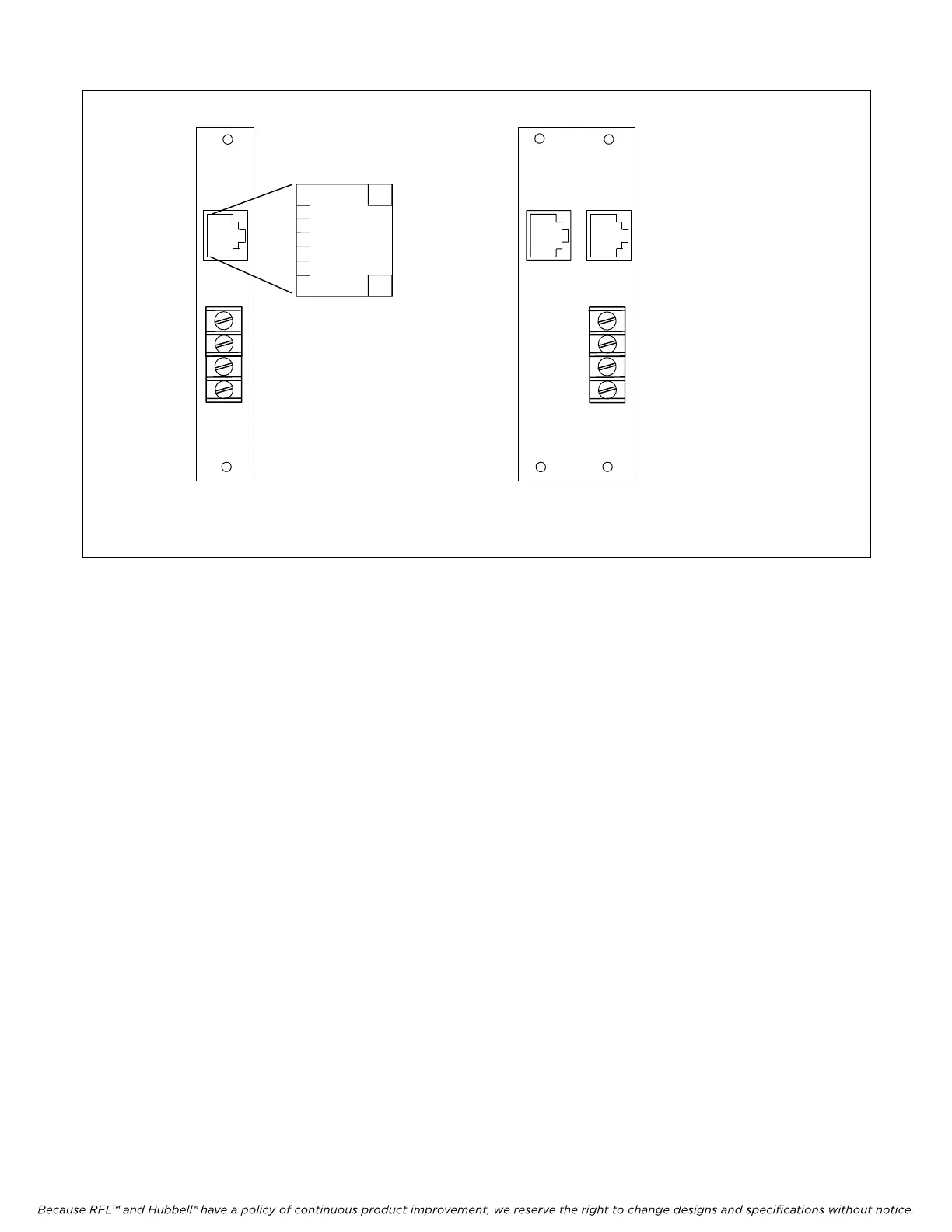
No.107655
Assembly
No.107655-1
1
2
5
6
3
4
VOICE CHANNEL
RING
TIP
MA-302
MA-302A
AC ONLY
AC ONLY
RING
GEN
RING
GEN
CH 1
FXS
CH 1
FXS
CH 2
FXS
TERMINAL BLOCK
CONNECTION FOR
EXTERNAL RING
GENERATOR
Figure 5. MA-302 and MA-302A, used with the RFL VF-16B station end modules.
4. Insert the Module Adapter into the rear of the shelf directly behind the module slot where the
RFL VF-16B module will be installed, and make all connections to the Module Adapter.
• If an MA-301 or MA-301C Module Adapter is being used, plug the 50-pin
Telco cable end connector into its mating 50-pin connector on the module
adapter. See Figure 1 and 2.
• If an MA-302, MA-302A Module Adapter is being used, plug the RJ-11
connector or connectors into the appropriate jack. Connect the external ring
generator to the terminal block connections as shown in Figure 5.
• If an MA-303 or 304 Module Adapter is being used, plug the RJ-11 (voice)
connectors into the appropriate jack. Connect to the bantam jacks for the
LINE and DROP channels as shown in Figure 3.
• If an MA-303B or MA-304B Adapter is being used, connect the voice channels
to the terminal blocks (TIP is the top terminal and RING is the bottom
terminal). Connect to the bantam jacks for the LINE and DROP channels as
shown in Figure 4.
RFL VF-16B RFL Electronics Inc.
January 17, 2007 10 (973)
334-3100