Because RFL™ and Hubbell® have a policy of continuous product improvement, we reserve the right to change designs and specifications without notice.
17
18
1
2
5
6
13
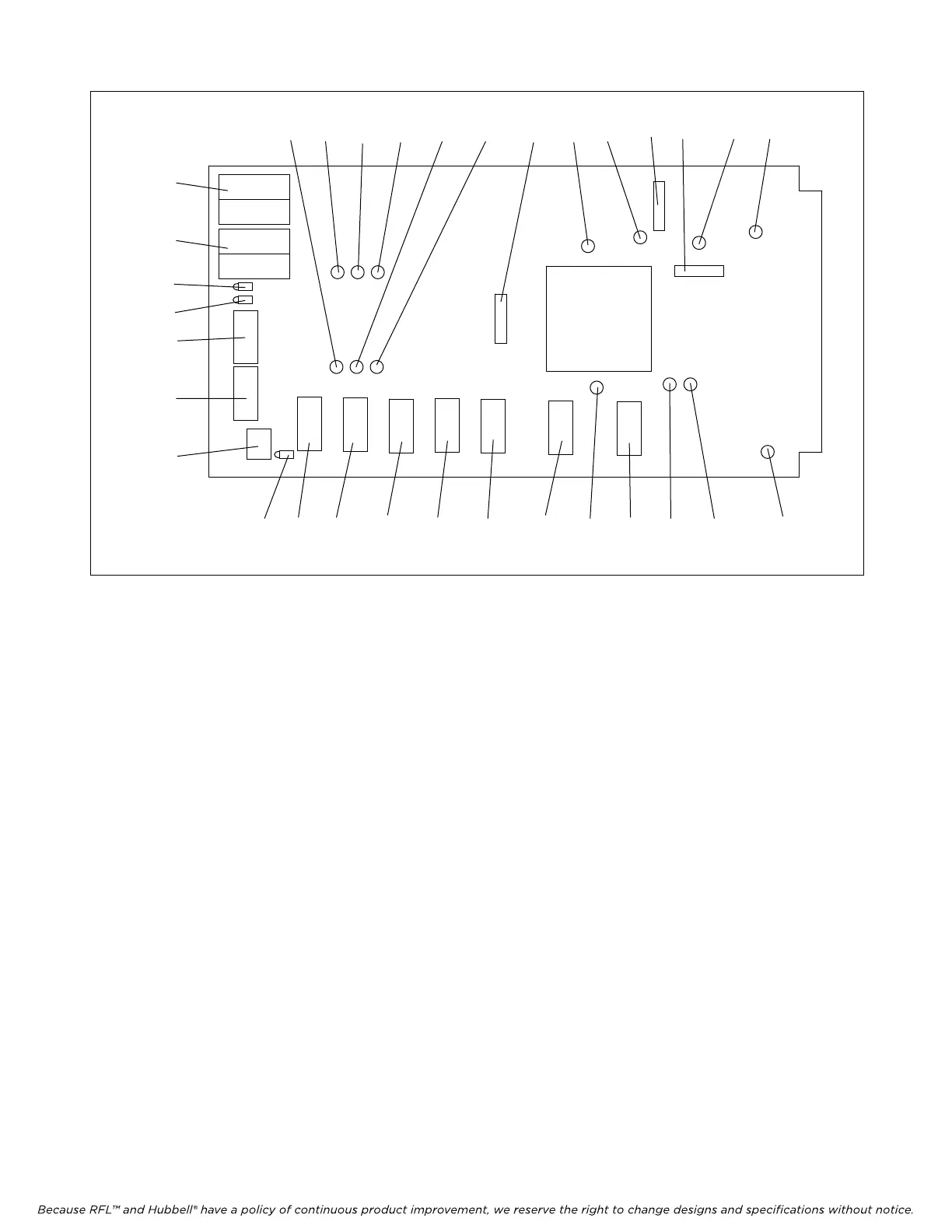
3 4 7 8 10 11 9 26 12 22 21 19
32 29 31 30 28 27 15 25 24 16 14 20 23
Figure 6. Controls and indicators, RFL VF-16B
11. Select any unused time slot for channel 2 using SW3-1 through SW3-5.
The digitized voice signal of each RFL VF-16B module occupies one 64-Kbps
digital time slot within the multiplexer’s aggregate rate. Use the settings shown in
Table 7 to select which time slot the module uses. Consult your multiplexer manual
for guidelines on time slot selection.
12. Select Channel 1 transmit direction using SW2-7.
Place SW2-7 in the UP position to transmit in the B direction and receive from the
A direction. Place SW2-7 in the DOWN position to transmit in the A direction and
receive from the B direction. Unless otherwise specified at time of order, SW2-7 is
set in the DOWN position at the factory.
13. Select Channel 2 transmit direction using SW3-7.
Place SW3-7 in the UP position to transmit in the B direction and receive from the
A direction. Place SW3-7 in the DOWN position to transmit in the A direction and
receive from the B direction. Unless otherwise specified at time of order, SW3-7 is
set in the DOWN position at the factory.
14. Enable or disable Automatic Ringdown (ARD) on Channel 1 by using DIP switch SW6-4.
Place SW6-4 in the OFF position for normal operation, or in the ON position for
ARD operation. Unless otherwise specified at time of order, SW6-4 is set in the
OFF position at the factory.
>> Text continues on page 17 <<
RFL VF-16B RFL Electronics Inc.
January 17, 2007 12 (973) 334-3100