Because RFL™ and Hubbell® have a policy of continuous product improvement, we reserve the right to change designs and specifications without notice.
RFL VF-16B RFL Electronics Inc.
January 17, 2007 13 (973) 334-3100
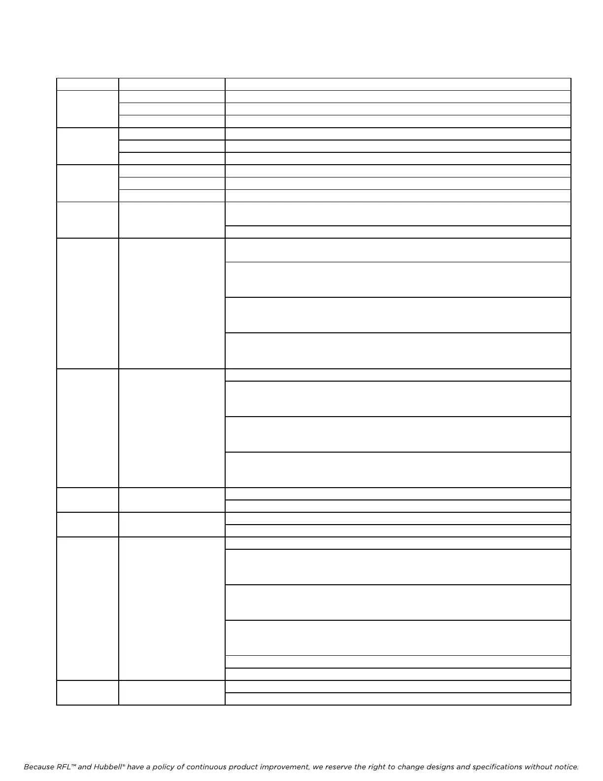
Table 1. Controls and indicators, RFL VF-16B modules
Item Name/Description Function
1 LED indicator (red)
Channel 1 busy (off hook). See Note A a
t the end of this table.
LED indicator (yellow) Channel 1 ringing.
LED indicator (green) Channel 1 enabled.
2 LED indicator (red)
Channel 2 busy (off hook). See Note A a
t the end of this table.
LED indicator (yellow) Channel 2 ringing.
LED indicator (green) Channel 2 enabled.
3 LED indicator (green) Top indicates module service is ON.
LED indicator (green) Middle not used.
LED indicator (green) Bottom not used.
4 DIP Switch SW1 SW1-1 to SW1-6: Sets SCB address (Table 2)
See Note A at the end of this table.
SW1-7 and SW1-8: Spare
5 DIP Switch SW2 SW2-1 to SW2-5: Sets Channel 1 Timeslot (Table 7)
See Note A at the end of this table.
SW2-6: Channel 1 enable/disable
UP: Channel 1 enabled
DOWN: Channel 1 disabled
SW2-7: Sets Channel 1 bus transmit direction
UP: “B” direction (D & I only)
DOWN: “A” direction (required for terminal multiplexer)
SW2-8: Enables or disables Channel 1 loopback
UP: Channel 1 loopback disabled
DOWN: Channel 1 loopback enabled
6 DIP Switch SW3 SW3-1 to SW3-5: Sets Channel 2 Timeslot (Table 7)
SW3-6: Channel 2 enable/disable
UP: Channel 2 enabled
DOWN: Channel 2 disabled
SW3-7: Sets Channel 2 bus transmit direction
UP: “B” direction (D & I only)
DOWN: “A” direction (required for terminal multiplexer)
SW3-8: Enables or disables Channel 2 loopback
UP: Channel 2 loopback disabled
DOWN: Channel 2 loopback enabled
7 DIP Switch SW4 SW4-1 to SW4-6 Sets Channel 1 Tx level (Table 3)
SW4-7 and SW4-8 Spare
8 DIP Switch SW5 SW5-1 to SW5-6 Sets Channel 1 Rx level (Table 3)
SW5-7 and SW5-8 Spare
9 DIP Switch SW6
SW6-1 and SW6-2 Channel 1 Ring Voltage (Table 4) See Note B b
elow
SW6-3 Channel 1 Ring DC Offset See Note B below
ON: enables DC offset (Table 4)
OFF: disables DC offset
SW6-4 Channel 1 Automatic Ring Down
ON: enables ARD
OFF: disables ARD
SW6-5 Channel 1 Loop Current
ON: Loop current = 41 mA
OFF: Loop current = 20 mA
SW6-6 and SW6-7 Channel 1 Ring Delay (Table 5)
SW6-8 Spare
10 DIP Switch SW7 SW7-1 to SW7-6 Sets Channel 2 Tx level (Table 3)
SW7-7 and SW7-8 Spare
Note B – When using module adapter MA-302 or MA-302A always set to the factory default.