Because RFL™ and Hubbell® have a policy of continuous product improvement, we reserve the right to change designs and specifications without notice.
RFL DS-TT RFL Electronics Inc.
January 31, 2008 6 (973) 334-3100
11 2 13 NOT USED 14
12
3
4
5
6
7
8
9
10
1
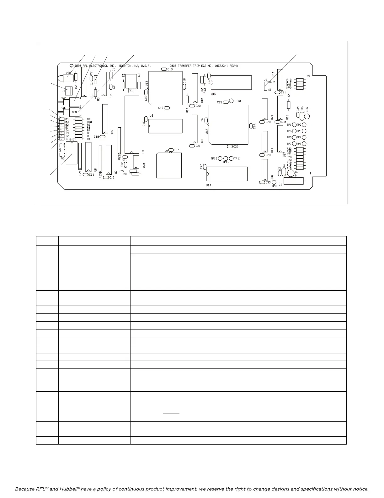
Figure 1. Controls and indicators, RFL DS-TT Transfer Trip Module.
Table 1. Controls and indicators, RFL DS-TT Transfer Trip Module
Item Name/Description Function
1 DIP Switch SW1 SW1-1 to SW1-5: Sets the SCB Address in accordance with Table 3.
SW1-6: Sets Transfer Trip module to Local or Remote mode.*
DOWN = Sets module to Local mode (settings can be m
ade using DS-TT
local RS-232 port)
UP = Sets module to Remote mode (settings can be made using CM3 remote
RS-232 port)
2 Switch SW2
(See Note 6 on page 27)
Disable Switch. Is used to disable the module. It disables all trip outputs and all
communications via the T1/E1 system. UP = ENABLE, DOWN = DISABLE
3 LED indicator (red) Lights when function 4 trip is received
4 LED indicator (red) Lights when function 3 trip is received
5 LED indicator (red) Lights when function 2 trip is received
6 LED indicator (red) Lights when function 1 trip is received
7 LED indicator (red) Lights when function 4 trip is transmitted
8 LED indicator (red) Lights when function 3 trip is transmitted
9 LED indicator (red) Lights when function 2 trip is transmitted
10 LED indicator (red) Lights when function 1 trip is transmitted
11 LED indicator (red) Lights during Alarm conditions and during programming
Note: Effective with software version SW2000TT021 LED will blink slowly
when m
odule is out of service.
12 Connector J1 An RS-232 port to connect a PC, Laptop or dumb terminal to the module. The RS-
232 port always operates using 8 data bits, no parity, and 1 stop bit. These
parameters
cannot
be changed by the user. The baud rate is set at 9600.
(See note on page 1) (See Figure 2 for cable details)
13 Jumper J2 Enables or disables the watchdog timer. Used for factory testing only. Should
always be in “RUN” (DOWN) position.
14 Jumper J3 Selects Relay or Solid-State output
* SW1-6 is used only on units with software version SW2000TT008 or higher.