Because RFL™ and Hubbell® have a policy of continuous product improvement, we reserve the right to change designs and specifications without notice.
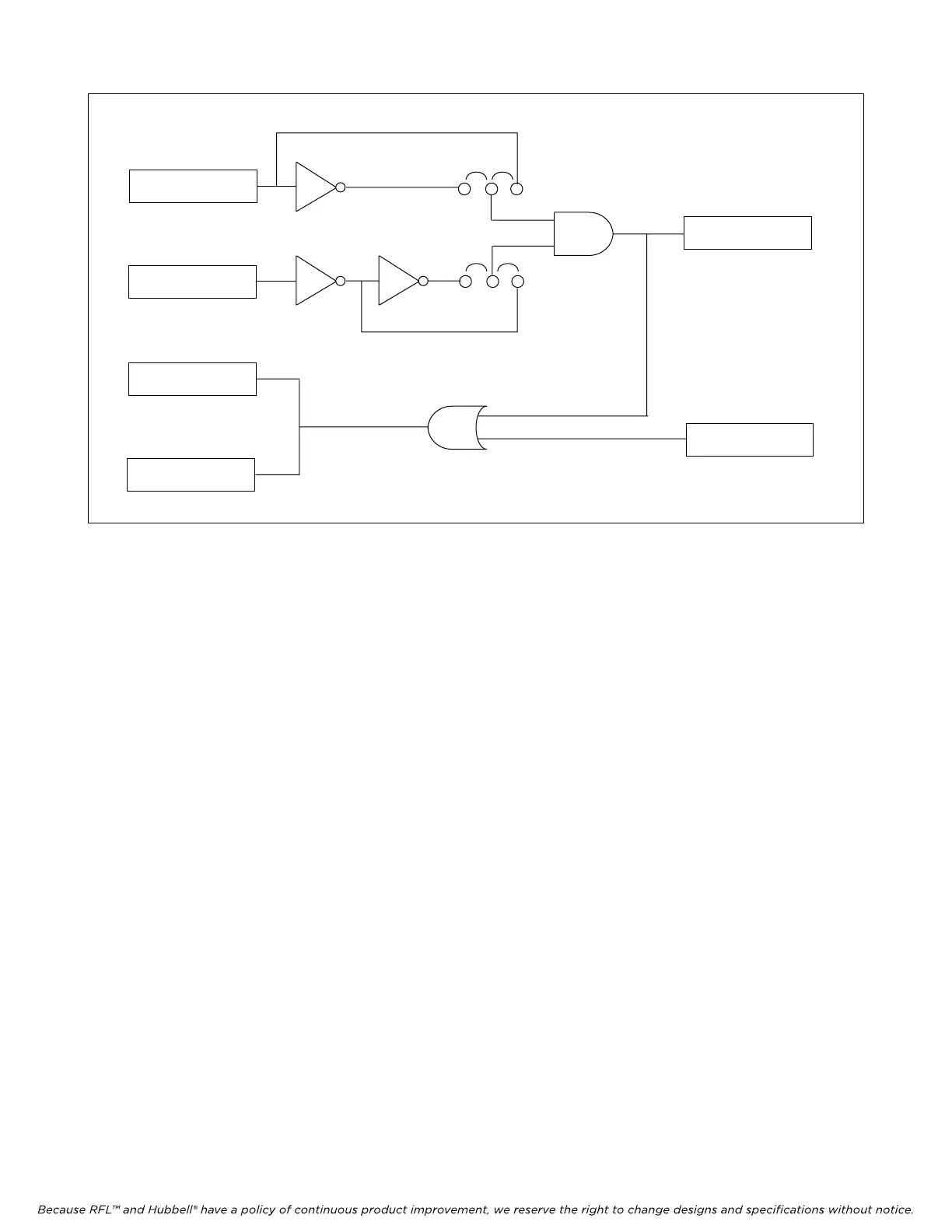
Input 1 (start)
Input 2 (stop)
Output 1
Output 2
Tx Function 1
Rx Function 1
J1
J2
Figure 7. Directional Comparison Blocking, block diagram
The MTS module retains all of its existing functionality and operates in DCB mode only if
commanded to. Otherwise the four functions operate as independent transfer trip commands. DCB
mode is invoked by setting P13 bit 6 to a 1. This can be done directly or via NMS.
Once in DCB mode the meaning of P7 bit 0 and P7 bit 1 change. In normal mode these bits set the
polarity of outputs 1 and 2. In DCB mode P7 bit 0 now selects the polarity of the start input and P7 bit
1 selects the polarity of the stop input. Both polarities are normal if the bit is a zero and inverted if the
bit is a one. To set these bits in NMS one should select “output polarity” for output 1 or 2 and change
it appropriately.
In order to have NMS support this feature the data base must be changed. In the TT card settings a new
setting must be added. In the card master setting selection, the following format is required:
Dir Comp Block⎟ setting⎟ choose2⎟ on⎟off ⎟ default = off⎟ P13=?1??????⎟ P13=?0??????
This will cause the NMS to bring up the directional comparison blocking on/off choice.
ALERTS AND ALARMS
If there is a loss of CRC or addressing, or if the disable switch is down, the transfer trip module will
issue a module alert signal to the shelf common module. This applies only to CM3Rs Rev H or higher,
and to transfer trip modules with software version SW2000TT008 or higher.
RFL DS-TT RFL Electronics Inc.
January 31, 2008 15 (973) 334-3100