Because RFL™ and Hubbell® have a policy of continuous product improvement, we reserve the right to change designs and specifications without notice.
BOARD CONFIGURATION
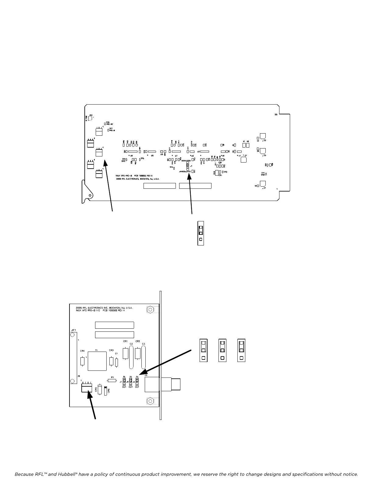
The Jumper (J1) on the MTS IRIG-B main module can be set for either Modulated or Unmodulated
IRIG-B depending on the source signal. Connectors J2 thru J6 are used to distribute unmodulated
IRIG-B to a maximum of five Transfer Trip (MTS) modules in the IMUX chassis.
MTS IRIG-B Module
(108000)
MODULATED
UNMODULATED
J2 thru J6 for connection to
Transfer Trip (MTS)
Modules
J1
Jumper shown in the
Modulated position
LOCATION FOR
PART NUMBER &
REV
LABEL
LOCATION FOR
SERIAL NUMBER
LABEL
J2
J3
J4
J5
J6
The three Jumpers on the IRIG-B I/O Board must all be set to either of the following depending on the
source signal.
IN – Modulated Signal (Bi-Polar)
OUT – Unmodulated Signal (TTL)
J1
J2 J3
IN
OUT OUT
OUT
IN
IN
Jumpers shown in the
Modulated position
J5 connects to second
IMUX Chassis in Daisy
Chain applications
LOCATION FOR
PART NUMBER & REV
LABEL
LOCATION FOR
SERIAL NUMBER LABEL
.01U
F
10
0
P6KE16C
A
P6KE16C
A
SB160
.0068UF
1KV
.0068UF
1KV
CONN. JK,FEM 30P
RA
10172
3
1.5KE
400CA
1.5KE
400CA
P6K
E
6.8AT
R
95595
J5
IRIG-B I/O Module (108005)
RFL DS-TT RFL Electronics Inc.
January 31, 2008 36 (973)
334-3100