Because RFL™ and Hubbell® have a policy of continuous product improvement, we reserve the right to change designs and specifications without notice.
RFL TMX/TMR RFL Electronics Inc.
January 25, 2012 19 (973)
334-3100
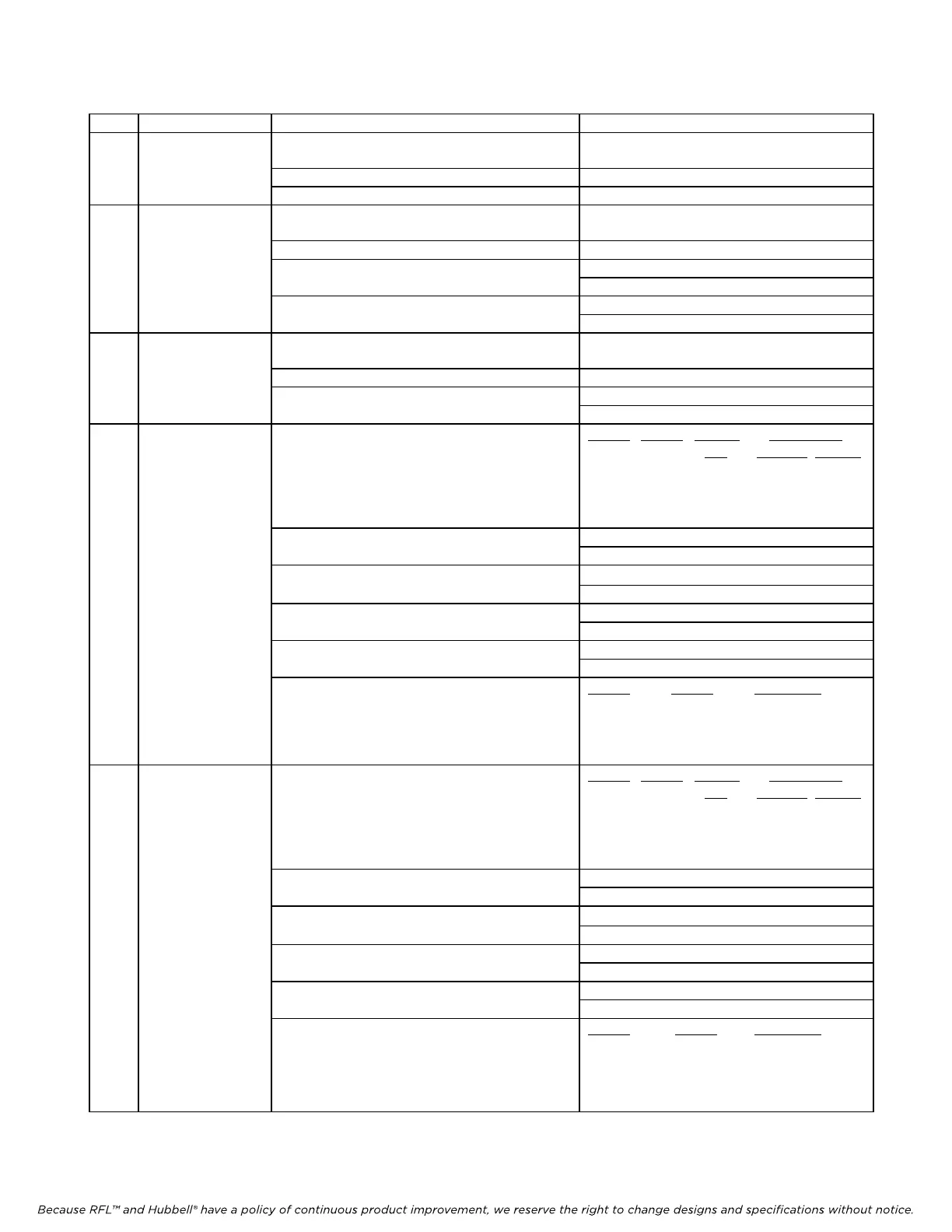
Table 10. Controls and indicators, RFL TMR Telemetry Receiver module
Item Name/Description Function Setting
1 DIP switch SW1 (SW1-1 Selects SCB address
thru - 6)
See Table 6
SW1-7 Spare NA
SW1-8 Spare NA
2 DIP switch SW2 (SW2-1 Time slot select
thru - 5)
See Table 7
SW2-6 Spare NA
SW2-7 Selects Local or Remote control UP: Remote control
DOWN: Local control
SW2-8 Sets module service ON or OFF UP: Service ON
DOWN: Service OFF
3 DIP Switch SW3 (SW3-1 Selects TMR address See Table 8
thru -6)
SW3-7 Spare NA
SW3-8 Selects Term/DIA or DIB 0 = DIB
1 = Terminal/DIA
4 DIP Switch SW4 (SW4-1 Selects analog channel 1 transfer ratio
and –2)
SW4-1 SW4-2 transfer NMS values
ratio
MS byte LS byte
0 0 1 8 0
0 1 2 16 0
1 0 4 32 0
1 1 ½ 4
0
SW4-3 Selects analog channel 1 offset 0 = 0 % (0 mA at D/A)
1 = +16 % (8 mA at D/A)
SW4-4 Selects analog channel 1 loss of
0 = previous value
signal output 1 = 0 %
SW4-5 Selects analog channel 1 output set to 0 = live data
fixed value 1 = forces output to fixed value
SW4-6 Selects analog channel 1 output level 0 = - 100 %
when fixed value is selected 1 = + 100 %
(SW4-7 Selects analog channel 1 output gain
and –8)
SW4-7 SW4-8 output gain
0 0 1
0 1 1/2
1 0 1/4
1 1 1/8
5 DIP Switch SW5 (SW5-1 Selects analog channel 2 transfer ratio
and –2)
SW5-1 SW5-2 transfer NMS values
ratio
MS byte LS byte
0 0 1 8 0
0 1 2 16 0
1 0 4 32 0
1 1 ½ 4
0
SW5-3 Selects analog channel 2 offset 0 = 0 % (0 mA at D/A)
1 = +16 % (8 mA at D/A)
SW5-4 Selects analog channel 2 loss of
0 = previous value
signal output 1 = 0 %
SW5-5 Selects analog channel 2 output set to 0 = live data
fixed value 1 = forces output to fixed value
SW5-6 Selects analog channel 2 output level 0 = - 100 %
when fixed value is selected 1 = + 100 %
(SW5-7 Selects analog channel 2 output gain
and –8)
SW5-7 SW5-8 output gain
0 0 1
0 1 1/2
1 0 1/4
1 1 1/8