Because RFL™ and Hubbell® have a policy of continuous product improvement, we reserve the right to change designs and specifications without notice.
RFL TMX/TMR RFL Electronics Inc.
January 25, 2012 20 (973) 334-3100
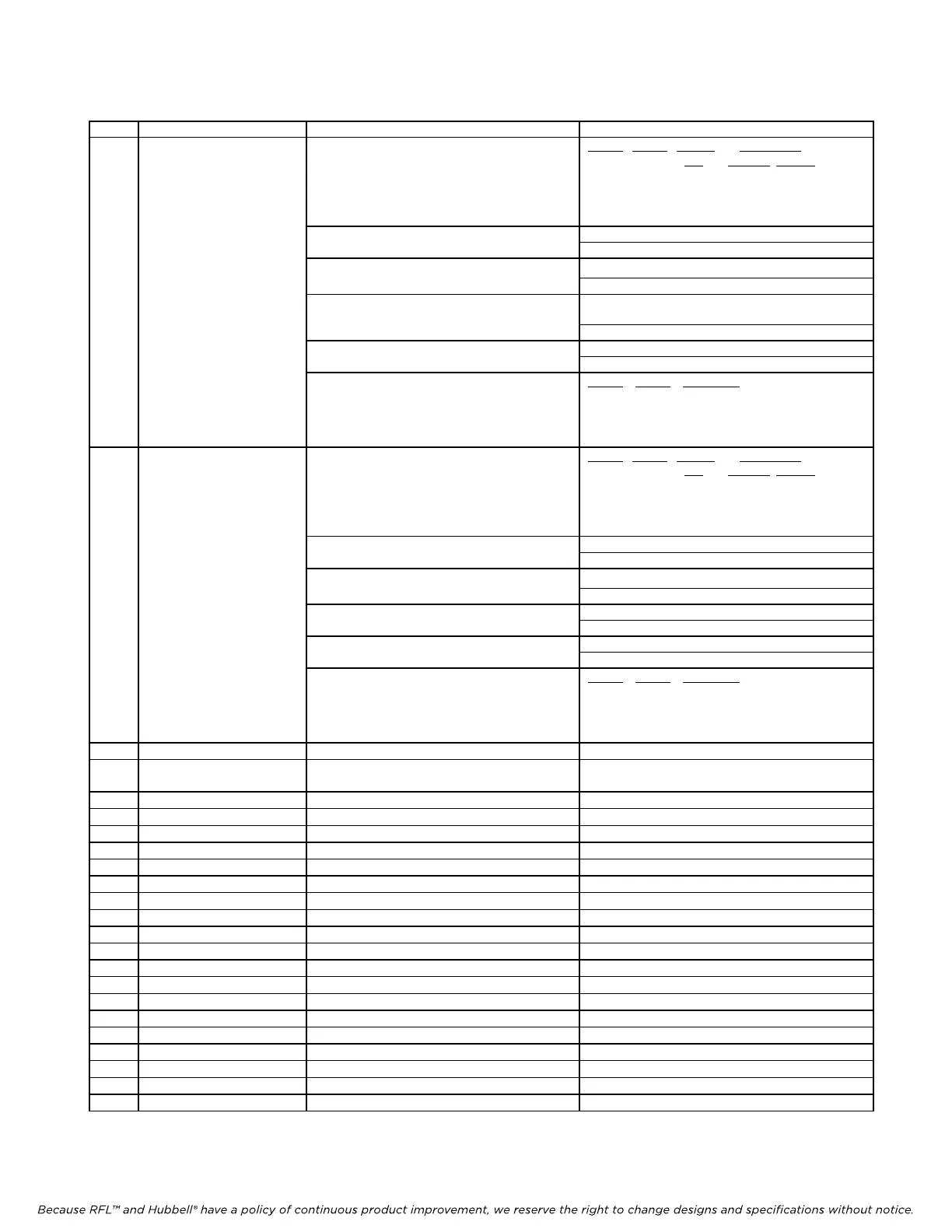
Table 10. continued - Controls and indicators, RFL TMR Telemetry Receiver module
Item Name/Description Function Setting
6 DIP Switch SW6 (SW6-1 Selects analog channel 3 transfer
and –2) ratio
SW5-1
SW5-2 transfer NMS values
ratio
MS byte LS byte
0 0 1 8 0
0 1 2 16 0
1 0 4 32 0
1 1 ½ 4 0
SW6-3 Selects analog channel 3 offset 0 = 0 % (0 mA at D/A)
1 = +16 % (8 mA at D/A)
SW6-4 Selects analog channel 3 loss of
0 = previous value
signal output 1 = 0 %
SW6-5 Selects analog channel 3 output set
to fixed value
0 = live data
1 = forces output to fixed value
SW6-6 Selects analog channel 3 output level 0 = - 100 %
when fixed value is selected 1 = + 100 %
(SW6-7 Selects analog channel 3 output gain
and –8)
SW6-7 SW6-8 output gain
0 0 1
0 1 1/2
1 0 1/4
1 1 1/8
7 DIP Switch SW7 (SW7-1 Selects analog channel 4 transfer
and –2) ratio
SW5-1 SW5-2 transfer NMS values
ratio
MS byte LS byte
0 0 1 8 0
0 1 2 16 0
1 0 4 32 0
1 1 ½ 4 0
SW7-3 Selects analog channel 4 offset 0 = 0 % (0 mA at D/A)
1 = +16 % (8 mA at D/A)
SW7-4 Selects analog channel 4 loss of
0 = previous value
signal output 1 = 0 %
SW7-5 Selects analog channel 4 output set 0 = live data
to fixed value 1 = forces output to fixed value
SW7-6 Selects analog channel 4 output level 0 = - 100 %
when fixed value is selected 1 = + 100 %
(SW7-7 Selects analog channel 4 output gain
and –8)
SW7-7 SW7-8 output gain
0 0 1
0 1 1/2
1 0 1/4
1 1 1/8
8 LED indicator DS1 (green) Service indicator Lit when module is in service
9 LED indicator DS2 (green) Address indicator Lit when TMX address matches TMR address or
if address test is disabled (local address = 0)
10 LED indicator DS3 (green) Lock indicator Lit when data frame lock is achieved
11 Potentiometer R8 D/A converter gain adjust Factory adjustment
12 Potentiometer R9 D/A converter offset adjust Factory adjustment
13 Potentiometer R18 Channel 1 offset adjust Factory adjustment
14 Potentiometer R20 Channel 2 offset adjust Factory adjustment
15 Potentiometer R22 Channel 3 offset adjust Factory adjustment
16 Potentiometer R24 Channel 4 offset adjust Factory adjustment
17 Test point TP1 Ground Ground
18 Test point TP2 D/A reference ground D/A reference ground
19 Test point TP3 Output of D/A converter Factory use only
20 Test point TP4 Output of attenuator Factory use only
21 Test point TP5 Output of channel 1 low pass filter Reading depends on signal
22 Test point TP6 Output of channel 2 low pass filter Reading depends on signal
23 Test point TP7 Output of channel 3 low pass filter Reading depends on signal
24 Test point TP8 Output of channel 4 low pass filter Reading depends on signal
25 Test point TP9 High side of current output for channel 1 Reading depends on load
26 Test point TP10 High side of current output for channel 2 Reading depends on load
27 Test point TP11 High side of current output for channel 3 Reading depends on load
28 Test point TP12 High side of current output for channel 4 Reading depends on load