Because RFL™ and Hubbell® have a policy of continuous product improvement, we reserve the right to change designs and specifications without notice.
App Note B: Monitoring RS232 Levels as Alarms
SNMP Access Gateway User’s Manual - v1.0 -- 11/99 - Page 51
App Note B: Monitoring RS232 Levels as
Alarms
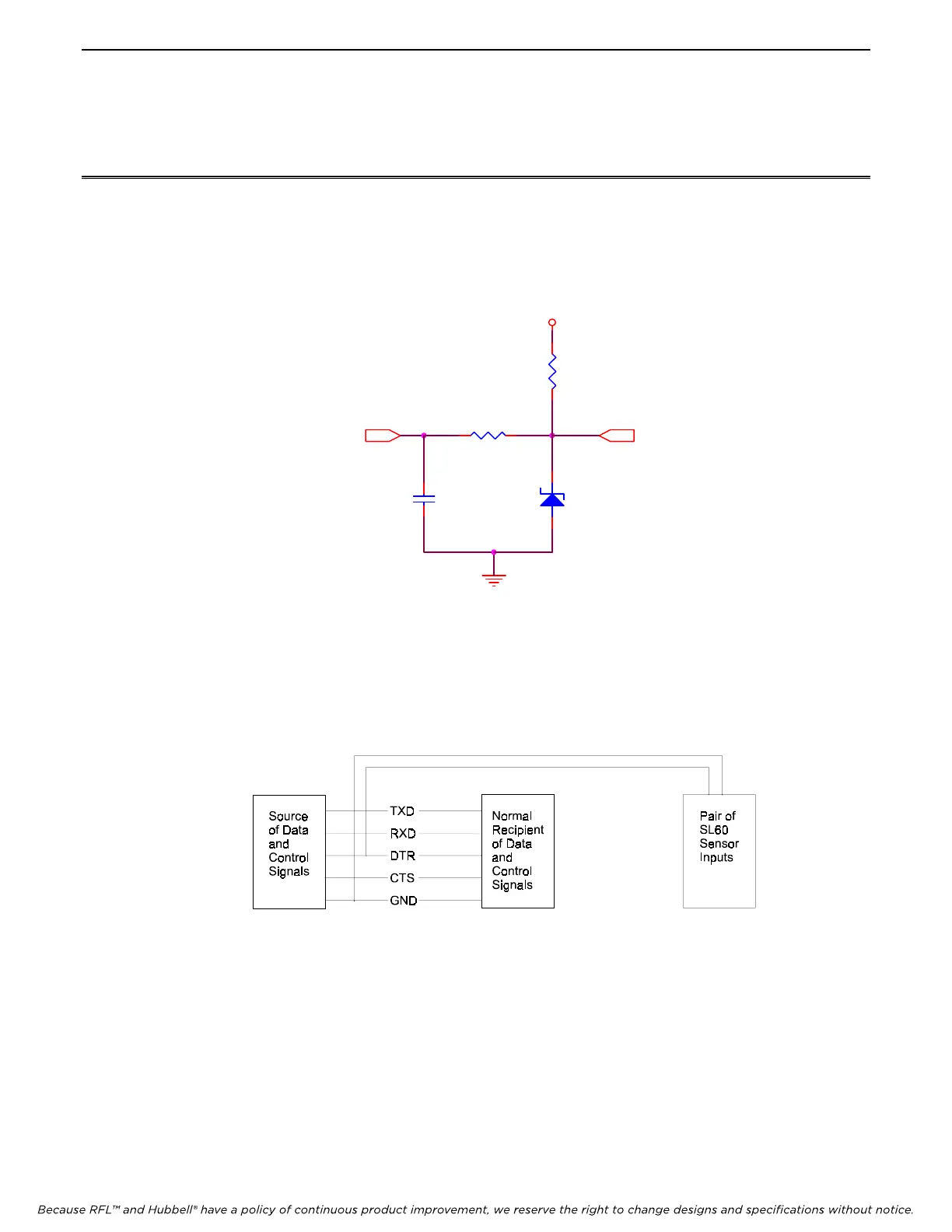
Th
e following diagram shows the circuit design of the Sensor Inputs. This design allows these inputs to be used
either as a dry contact closure input, or as an analog input.
VCC
5.1V
12
100K
1 2
4.7K
1 2
100pF
1 2
A/DIN
Figure 8. Schematic for Sensor Inputs
Se
nsor inputs can be used to monitor the state of an RS232 control line such as DTR. A wire can be attached to the
line to be monitored and routed to one of the sensor inputs. The Sensor Input should be set to operate as a ‘Contact
Closure’, not an ‘Analog Input’. When the control line is LOW the contact input will be seen as OPEN. When the
control line is HIGH the contact input will be seen as CLOSED.
Figure 9. Illustration of Connecting for Monitoring RS232 Control Lines
No
te that RS232 control signal lines are not specifically designed to drive more that one input, therefore connecting
the output signal to two input connections will cause the overall voltage level of the RS232 control line to be lower
that it otherwise would being connected to a single input. This circumstance will vary from device to device and in
19 out of 20 cases should not present any problem. However you should be aware of this factor if you experience
any problems with the other device which would normally be the single device receiving the RS232 output signal
you are monitoring.