U.4.11
Date Code 20090715 User’s Guide SEL-421 Relay
Basic Relay Operations
Checking Relay Status
Step 2. Type STA <Enter>. The relay returns a status terminal screen
similar to that in Figure 4.6.
=>STA <Enter>
Relay 1 Date: 03/15/2001 Time:07:02:50.776
Station A Serial Number: 000101234
FID=SEL-421-R101-V0-Z001001-D20010315 CID=0x9aed
Failures
No Failures
Warnings
No Warnings
SELogic Relay Programming Environment Errors
No Errors
Relay Enabled
=>
Figure 4.6 Relay Status
Step 3. Type STA A <Enter> to view all relay status entries.
For more information on relay status report items, see STATUS
on page R.9.48.
Checking Relay
Status: ACSELERATOR
QuickSet
You can use ACSELERATOR QuickSet to check relay status. Use the HMI >
Meter Control menu to view status conditions.
The procedure in the following steps assumes that you have successfully
established communication with the relay (see Making an EIA-232 Serial Port
Connection on page U.4.5). In addition, you must be familiar with relay
access levels and passwords (see Changing the Default Passwords: Terminal
on page U.4.9 to change the default access level passwords). You should also
be familiar with
ACSELERATOR QuickSet (see Section 3: PC Software).
Step 1. Configure the communications port.
a. Start
ACSELERATOR QuickSet.
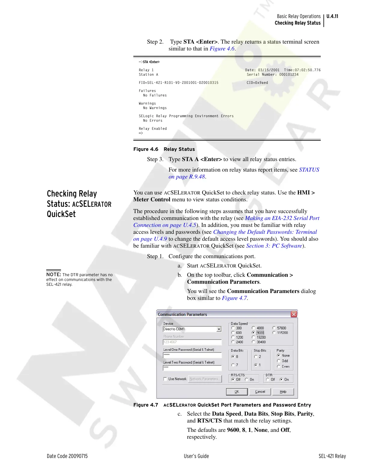
b. On the top toolbar, click Communication >
Communication Parameters.
You will see the Communication Parameters dialog
box similar to Figure 4.7.
Figure 4.7 ACSELERATOR QuickSet Port Parameters and Password Entry
c. Select the Data Speed, Data Bits, Stop Bits, Parity,
and RTS/CTS that match the relay settings.
The defaults are 9600, 8, 1, None, and Off,
respectively.
NOTE: The DTR parameter has no
effect on communications with the
SEL-421 relay.
Courtesy of NationalSwitchgear.com