U.6.30
SEL-421 Relay User’s Guide Date Code 20090715
Testing and Troubleshooting
Checking Relay Operation
Checking the Negative-Sequence Directional Element (Phase Faults)
NOTE: As you perform this test,
other protection elements can assert.
This causes the relay to assert other
targets and possibly close control
outputs. Be sure to isolate the relay
from the power system to avoid
unexpected system effects.
This test confirms operation of the F32Q and the R32Q negative-sequence
directional elements. This test procedure is for a 5 A relay; scale values
appropriately for a 1 A relay.
This example assumes that you have successfully established communication
with the relay (see Making an EIA-232 Serial Port Connection on page U.4.5).
In addition, you must be familiar with relay access levels and passwords (see
Changing the Default Passwords on page U.4.6 to change the default access
level passwords and enter higher relay access levels). You should be familiar
with
ACSELERATOR QuickSet (see Section 3: PC Software).
Step 1. Configure the relay.
a. Open
ACSELERATOR QuickSet and read the present
configuration in the SEL-421.
b. Click Settings > Read.
The relay sends all settings and configuration data to
ACSELERATOR QuickSet.
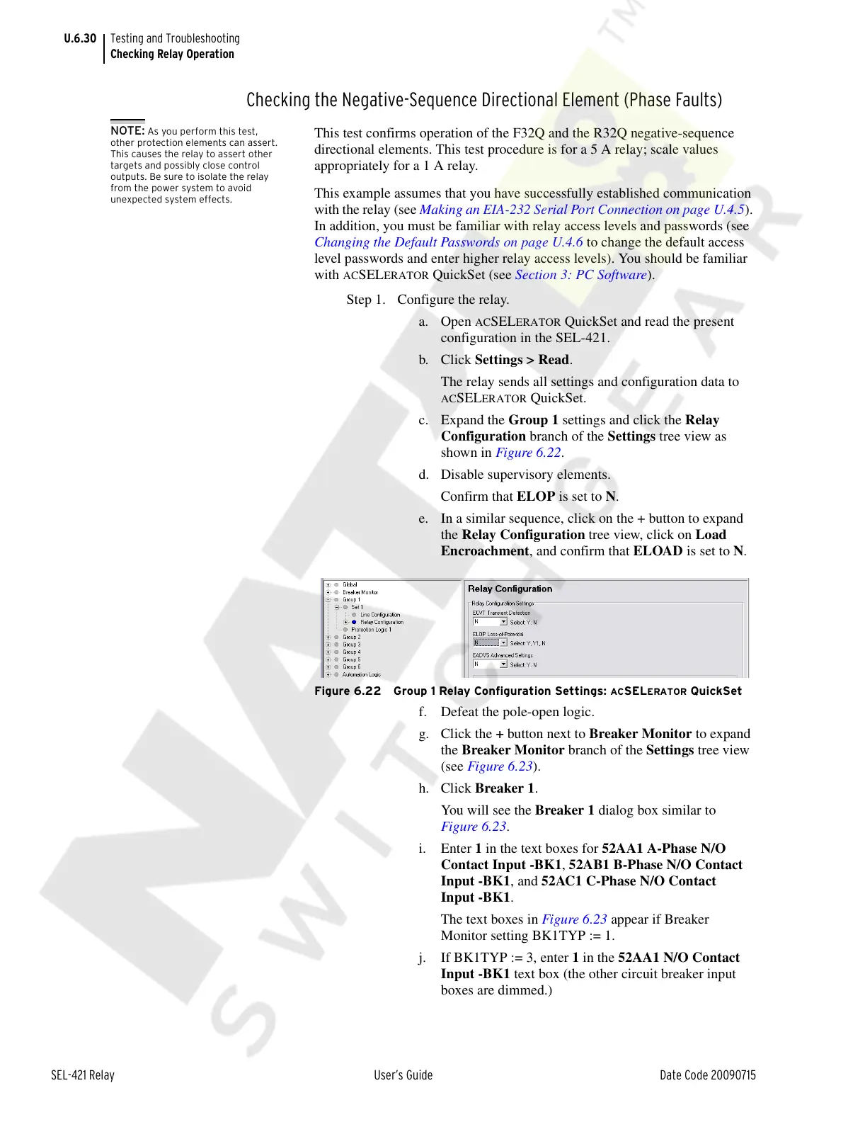
c. Expand the Group 1 settings and click the Relay
Configuration branch of the Settings tree view as
shown in Figure 6.22.
d. Disable supervisory elements.
Confirm that ELOP is set to N.
e. In a similar sequence, click on the + button to expand
the Relay Configuration tree view, click on Load
Encroachment, and confirm that ELOAD is set to N.
Figure 6.22 Group 1 Relay Configuration Settings: ACSELERATOR QuickSet
f. Defeat the pole-open logic.
g. Click the + button next to Breaker Monitor to expand
the Breaker Monitor branch of the Settings tree view
(see Figure 6.23).
h. Click Breaker 1.
You will see the Breaker 1 dialog box similar to
Figure 6.23.
i. Enter 1 in the text boxes for 52AA1 A-Phase N/O
Contact Input -BK1, 52AB1 B-Phase N/O Contact
Input -BK1, and 52AC1 C-Phase N/O Contact
Input -BK1.
The text boxes in Figure 6.23 appear if Breaker
Monitor setting BK1TYP := 1.
j. If BK1TYP := 3, enter 1 in the 52AA1 N/O Contact
Input -BK1 text box (the other circuit breaker input
boxes are dimmed.)
Courtesy of NationalSwitchgear.com