R.1.71
Date Code 20111215 Reference Manual SEL-421 Relay
Protection Functions
Inverse-Time Overcurrent Elements
Symmetrical component current quantities are available only for the line
current source. Table 1.56 defines the available setting choices for operating
quantities and the corresponding analog quantity name as found in Table B.2.
Each time-overcurrent element has a torque control SEL
OGIC equation
51SkTC (k = 1–3) that enables the element when the equation evaluates to
logical 1, and disables the element when the equation evaluates to logical 0.
See Figure 1.58 for a logic diagram of the time-overcurrent elements,
including the torque control input.
The enable setting (E51S) controls how many time-overcurrent elements are
available. For example, if E51S := 1, only 51S1 is processed. The remaining
time-overcurrent elements 51Sk (k = 2–3) are defeated, and the output Relay
Word bits are forced to logical 0.
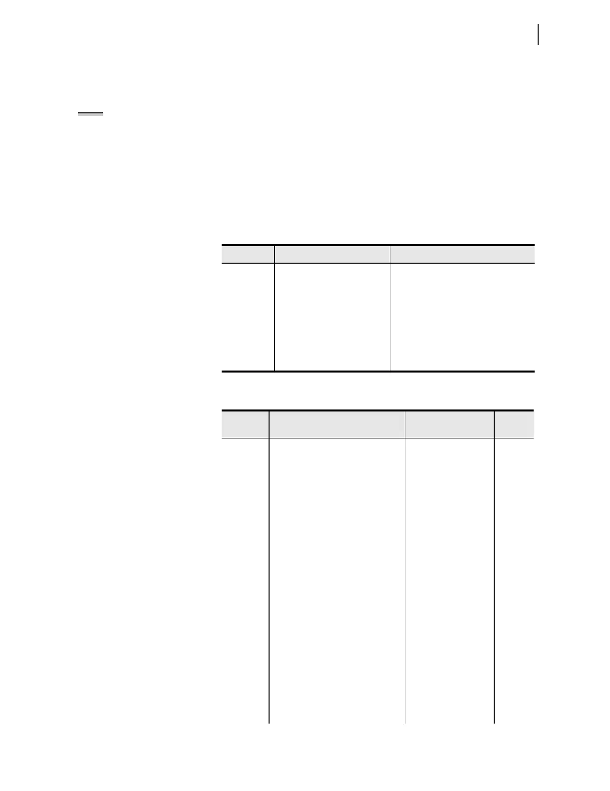
Table 1.56 Selectable Current Quantities
a
a
Parameter n is L for Line, 1 for Breaker 1, and 2 for Breaker 2.
Quantity Description Analog Quantities
IAn A-Phase LIAFIM, B1IAFIM, B2IAFIM
IBn B-Phase LIBFIM, B1IBFIM, B2IBFIM
ICn C-Phase LICFIM, B1ICFIM, B2ICFIM
IMAXn Maximum Phase
I1L Line positive-sequence current LI1FIM
3I2L Line negative-sequence current L3I2FIM
3I0n Zero-sequence current LIGFIM, B1IGFIM, B2IGFIM
Table 1.57 Selectable Inverse-Time Overcurrent Settings
a
(Sheet 1 of 2)
Setting Description Range
Default
(5 A)
E51S Selectable Inverse-Time Overcurrent
Element
N, 1–3 1
51S1O Operating Quantity Element 1 IAn, IBn, ICn, IMAXn,
I1L, 3I2L, 3I0n
3I0L
51S1P 51S1 O/C Pickup Element 1 (A) (0.05–3.2) • I
nom
0.75
51S1C 51S1 Inverse Time O/C Curve
Element 1
U1–U5
C1–C5
U3
51S1TD 51S1 Inverse Time O/C Time Dial
Element 1
0.50–15.00 (Ux)
b
0.05–1.00 (Cx)
b
1.0
51S1RS 51S1 Inverse Time O/C
Electromechanical Reset Element 1
Y, N N
51S1TC 51S1 Inverse Time O/C Torque
Control Element 1
SEL
OGIC Equation 32GF
51S2O Operating Quantity Element 2 IAn, IBn, ICn, IMAXn,
I1L, 3I2L, 3I0n
3I2L
51S2P 51S2 O/C Pickup Element 2 (A) (0.05–3.2) • I
nom
5.00
51S2C 51S2 Inverse Time O/C Curve
Element 2
U1–U5
C1–C5
U3
51S2TD 51S2 Inverse Time O/C Time Dial
Element 2
0.50–15.00 (Ux)
b
0.05–1.00 (Cx)
b
1
51S2RS 51S2 Inverse Time O/C
Electromechanical Reset Element 2
Y, N N
NOTE: In the SEL-421, the time-
overcurrent elements are not
directionally controlled in the internal
logic. Directional control may be
achieved through the use of the
torque control settings, as shown in
Section 1: Protection Application
Examples in the Applications
Handbook. Also refer to
Directionality on page R.1.39.