R.3.28
SEL-421 Relay Reference Manual Date Code 20111215
SELOGIC Control Equation Programming
SELOGIC Control Equation Operators
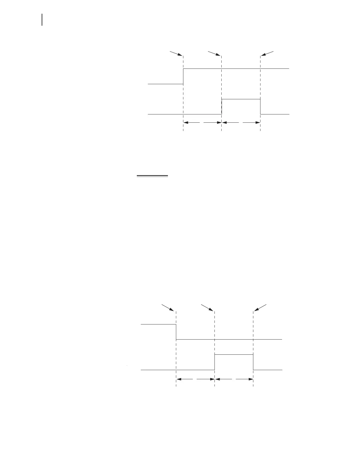
Figure 3.9 R_TRIG Timing Diagram
The argument of an R_TRIG statement must be a single bit within the
SEL-421. An example of the relay detecting a rising edge of a calculated
quantity is shown in Example 3.11.
EXAMPLE 3.11 R_TRIG Operation
The SEL
OGIC control equation below is invalid.
PSV15 := R_TRIG (PSV01 AND PSV23) # Invalid statement, do not use
Use a SELOGIC control equation variable to calculate the quantity and
then use the R_TRIG operation on the result, as shown below.
PSV14 := PSV01 AND PSV23 # Calculate quantity in an intermediate result
variable
PSV15 := R_TRIG PSV14 # Perform an R_TRIG on the quantity
F_TRIG
F_TRIG is a time-based function that creates a pulse when another value
changes, as shown in Example 3.11. Use F_TRIG to sense when a value
changes from logical 1 to logical 0 and take action only after the value
changes state.
Figure 3.10 F_TRIG Timing Diagram
Relay Word bit
A
R_TRIG A
R_TRIG A
Deasserts
R_TRIG A
Asserts
Relay Word bit A Changes
from 0 to 1
1
Processing
Interval
1
Processing
Interval
Relay Word bit A
_TRIG A
F_TRIG A
Deasserts
F_TRIG A
Asserts
Relay Word bit A Changes
from 1 to 0
1
Processing
Interval
1
Processing
Interval