R.7.3
Date Code 20111215 Reference Manual SEL-421 Relay
Synchrophasors
Introduction
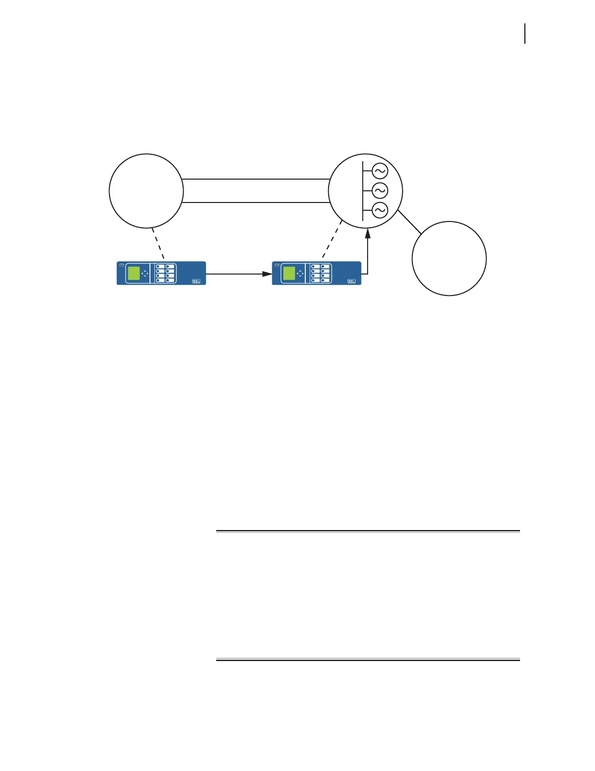
Figure 7.1 shows an application example. In this example, Area 2 supplies
power to Area 1 and Area 3. An important contingency is loss of both Link 1
and Link 2. In such a case, the generators in Area 2 accelerate. Alternate paths
between Area 2 and Area 1 can also become stressed beyond their design
limits. A simple solution is to measure the phase angle between Area 1 and
Area 2. When the angle exceeds a predetermined limit, control the generation
to avoid exceeding system limits.
Figure 7.1 Real-Time Control Application
Figure 7.2 shows the SELOGIC for the relay controlling the generator (called
the local relay in this example). Lines 1 and 2 store phasor data into PMV53
and PMV54 so they can be viewed through use of the MET PMV command.
Line 3 computes the angle difference between the local and remote relays.
Lines 4 through 10 unwrap the phase angle when the difference exceeds ±180
degrees.
Line 11 calculates a qualification signal consisting of the local and remote
quality indicators. RTCROKA is the local indicator. RTCAD16 is the remote
quality indicator. Figure 7.3 shows its construction at the remote relay.
Line 12 computes absolute value of the angle. Line 13 checks the angle
against the reference value. In this case, the reference value is 6 degrees. Lines
14 and 15 build a timer that operates after two successive messages in excess
of the threshold. On line 15, the value PSV05 tracks the last result of the angle
difference check.
The final result, PSV04, asserts when the SEL-421 receives two successive
synchrophasor messages with angle difference exceeding 6 degrees.
Protection 1
1: PMV53 := V1LPMAD
2: PMV54 := RTCAP02
3: PMV55 := V1LPMAD - RTCAP01
4: PSV01 := PMV55 >= 180.000000
5: PMV01 := -180.000000
6: PSV02 := PMV55 <= PMV01
7: PMV01 := PMV55 + 360.000000
8: PMV02 := PMV55 - 360.000000
9: PMV55 :=NOT PSV01*PMV55+PSV01*PMV02
10: PMV55 :=NOT PSV02*PMV55+PSV02*PMV01
11: PSV01 := RTCROKA AND RTCAD01
12: PMV56 := ABS(PMV55)
13: PSV03 :=(PMV56 > 10.000000) AND PSV01
14: PSV04 := PSV01 AND PSV03 AND PSV05
15: PSV05 := (NOT PSV01 AND PSV05 OR PSV01 AND PSV03)
Figure 7.2 Local Relay SELOGIC Settings
Area 2
SEL-421
SEL-421
Link 1
Link 2
Area 1
Heavy Load
Area 3
Light Load
Synchrophasors
Control
Generation