R.1.18
SEL-421 Relay Reference Manual Date Code 20111215
Protection Functions
Fault Location
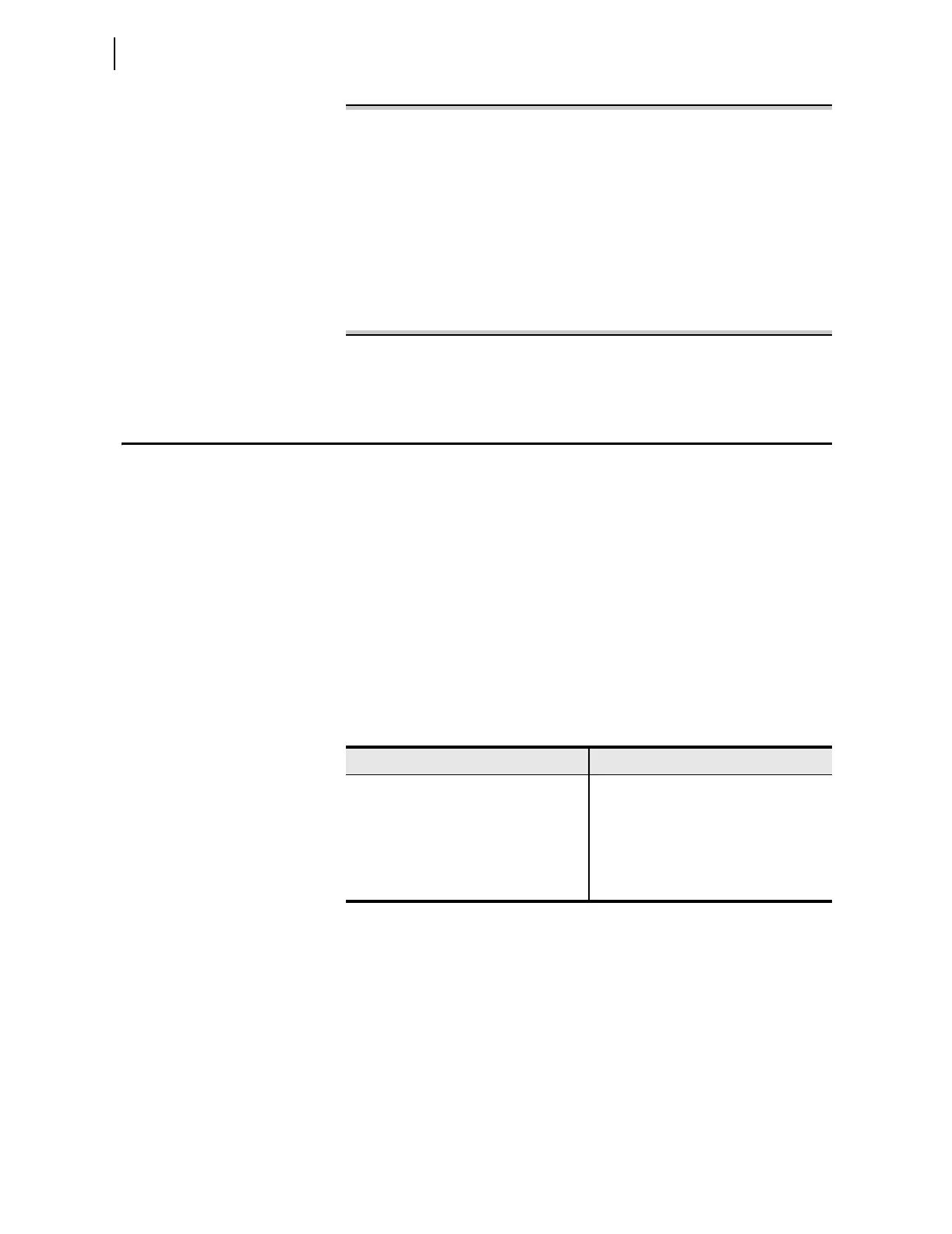
==>TEC 2.25 <Enter>
Relay 1 Date: 11/02/2004 Time: 11:53:12.701
Station A Serial Number: 0000000000
Change TECORR to 2.250 s:
Are you sure (Y/N)?Y <Enter>
Time Error Correction Preload Value
TECORR = 2.250 s
Relay Word Elements
LOADTE = 0, STALLTE = 0, FREQOK = 1
Accumulated Time Error
TE = -5.862 s
==>
Figure 1.14 Sample TEC
n
Command Response
Fault Location
The SEL-421 computes distance to fault from data stored in the event reports.
The relay calculates distance to fault upon satisfaction of all four of the
following conditions:
➤ The fault locator is enabled, setting EFLOC := Y.
➤ A single-pole open condition does not exist (i.e., Relay Word
bit SPO equals logical 0).
➤ A phase distance, ground distance, residual ground overcurrent,
negative-sequence, or time-overcurrent element picks up no
later than 15 cycles after the event report trigger.
➤ The fault duration is greater than one cycle, as determined by
the previously listed asserted protection element(s).
The relay calculates distance to fault in per unit of the positive-sequence line
impedance, Z
1
. Use the relay setting LL, Line Length, to determine the units
that the relay reports for the distance to a fault. For example, if a fault occurs
at the midpoint of the protected line and you set LL to 126 for a line length of
126 kilometers, the result of the relay distance-to-fault calculation is 63.
Distance-to-fault calculation results range from –999.99 to 999.99. If the
calculation cannot be determined (e.g., insufficient information) or if the
result is outside the specified range, the relay reports the fault location as
$$$$.$$.
Table 1.15 Fault Location Triggering Elements
Faul t Type Protection Element
Ground Faults Z1G–Z5G
67G1–67G4
67Q1–67Q4
51S1–51S3
a
a
Corresponding group setting 51SkO must be set to 3I2L or 3I0L (k = 1–3).
Phase Faults M1P–M5P
67Q1–67Q4
51S1–51S3
b
b
Corresponding group setting 51SkO must be set to IAL, IBL, ICL, I1L, 3I2L, or IMAXL (k = 1–3).