R.7.6
SEL-421 Relay Reference Manual Date Code 20111215
Synchrophasors
Synchrophasor Measurement
received. Use this command to ensure that the remote value that you chose for
the SEL
OGIC equation (for example, RTCAP01 in Figure 7.2) is the correct
value to compare with the local synchrophasor value.
The RTCDLYA bit asserts when synchrophasor data have not been received
within the window you set with the local MRTCDLY setting (100 ms in this
example). If the RTCDLYA asserts, consider three options. First, the
MRTCDLY setting can be increased. However, the MRTCDLY setting is your
way of guaranteeing operation within a certain time. Increasing MRTCDLY
allows for communication channels with longer transmission delay, but at the
cost of increasing the maximum time of operation. A second option is to
improve the communication channel so that it operates within the required
MRTCDLY setting time. A final option is available if the assertion of
RTCDLY results from a temporary communication channel disruption. In this
case, putting RTCDLYA in the SER provides warning.
The COM RTC command also provides information for monitoring system
status. Figure 7.8 shows a COM RTC command response. Use the maximum
packet delay field to monitor the communication channel delay. This
information can help you choose an appropriate value for the MRTCDLY
setting.
Summary for RTC channel A
Port: 2
ID: 8
Present Status: Receiving
Max Packet Delay: 50 msec
Message Rate: 60 msgs/sec
Summary for RTC channel B
Port: 1
ID: 9
Present Status: Receiving
Max Packet Delay: 40 msec
Message Rate: 60 msgs/sec
Figure 7.8 Example COM RTC Command Response
Synchrophasor Measurement
The phasor measurement unit in the SEL-421 measures three voltages and six
currents on a constant-time basis. These samples are synchronized to the high-
accuracy IRIG time source, and occur at a fixed frequency of either 60 Hz or
50 Hz, depending on Global setting NFREQ. The relay then filters the
measurement samples according to Global setting PMAPP := F or N—see
PMAPP on page R.7.10. The phase angle is measured relative to an absolute
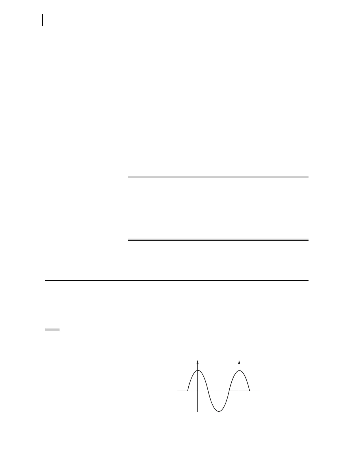
time reference, which is represented by a cosine function in Figure 7.9. The
time-of-day is shown for the two time marks.
Figure 7.9 High Accuracy Clock Controls Reference Signal (60 Hz System)
NOTE: The synchophasor data
stream is separate from the other
protection and metering functions, as
shown in Figure 3.1 on page A.3.3.
10:00:00.000000 10:00:00.016667
t