R.1.72
SEL-421 Relay Reference Manual Date Code 20111215
Protection Functions
Inverse-Time Overcurrent Elements
Time-Current
Operating
Characteristics
The following information describes curve timing for time-overcurrent
element curve and time-dial settings. The time-overcurrent relay curves in
Figure 1.48 through Figure 1.57 conform to IEEE C37.112–1996 IEEE
Standard Inverse-Time Characteristic Equations for Overcurrent Relays.
51S2TC 51S2 Inverse Time O/C Torque
Control Element 2
SELOGIC Equation 32QF
51S3O Operating Quantity Element 3 IAn, IBn, ICn, IMAXn,
I1L, 3I2L, 3I0n
IMAXL
51S3P 51S3 O/C Pickup Element 3 (A) OFF, (0.05–3.2) • I
nom
5.00
51S3C 51S3 Inverse Time O/C Curve
Element 3
U1–U5
C1–C5
U3
51S3TD 51S3 Inverse Time O/C Time Dial
Element 3
0.50–15.00 (Ux)
b
0.05–1.00 (Cx)
b
1
51S3RS 51S3 Inverse Time O/C
Electromechanical Reset Element 3
Y, N N
51S3TC 51S3 Inverse Time O/C Torque
Control Element 3
SEL
OGIC Equation M2P
a
Parameter n is L for Line, 1 for BK1, and 2 for BK2.
b
Parameter x is a number from 1—5 indicating the operating curve (see Figure 1.48 through
Figure 1.57).
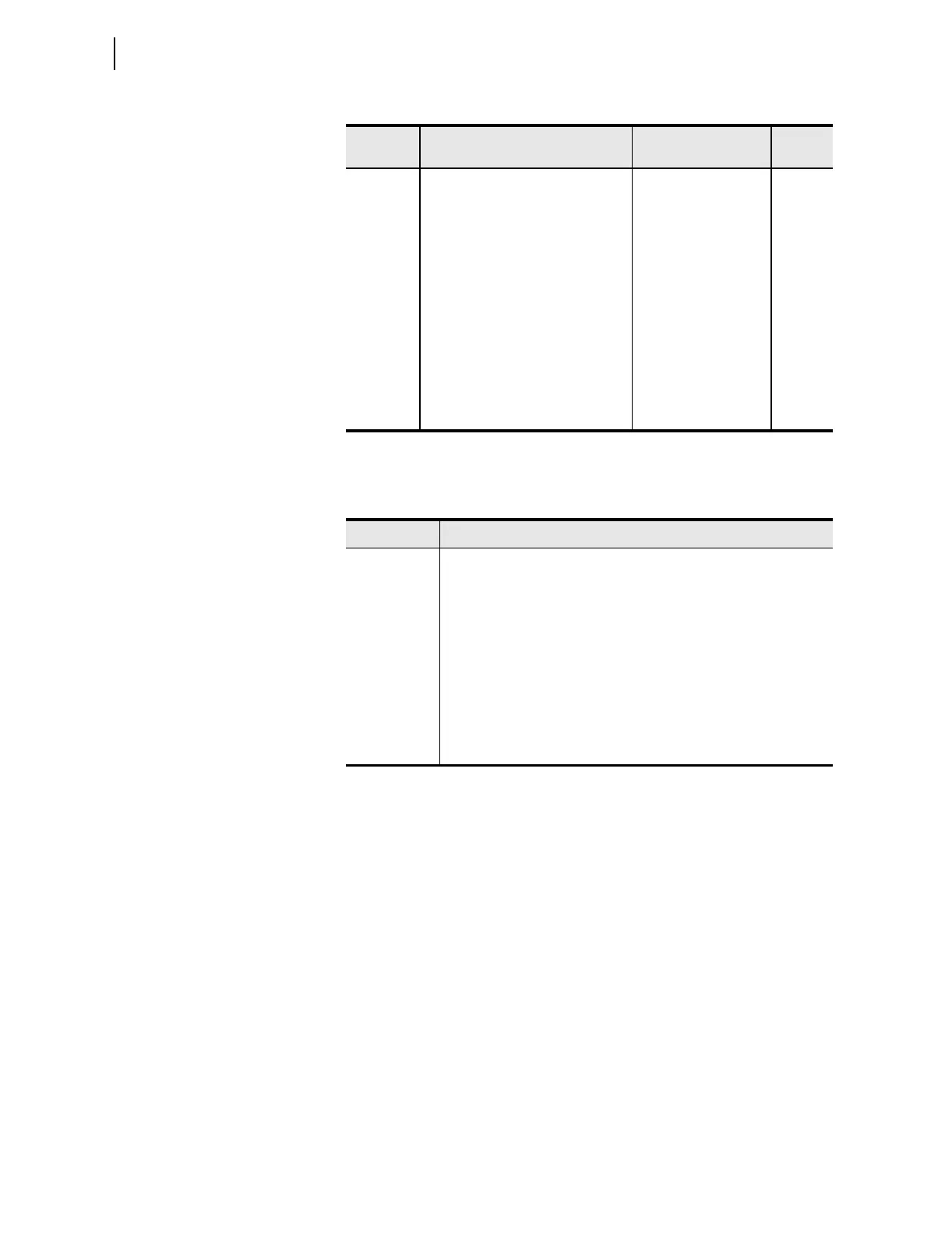
Table 1.58 Selectable Inverse-Time Overcurrent Relay Word Bits
Name Description
51S1 Inverse-Time Overcurrent Element 1 pick-up
51S1T Inverse-Time Overcurrent Element 1 timed out
51S1R Inverse-Time Overcurrent Element 1 reset
51S2 Inverse-Time Overcurrent Element 2 pick-up
51S2T Inverse-Time Overcurrent Element 2 timed out
51S2R Inverse-Time Overcurrent Element 2 reset
51S3 Inverse-Time Overcurrent Element 3 pick-up
51S3T Inverse-Time Overcurrent Element 3 timed out
51S3R Inverse-Time Overcurrent Element 3 reset
Table 1.57 Selectable Inverse-Time Overcurrent Settings
a
(Sheet 2 of 2)
Setting Description Range
Default
(5 A)
T
p
= operating time in seconds
T
r
= electromechanical induction-disk emulation reset time in
seconds (if you select electromechanical reset setting)
TD = time-dial setting
M = applied multiples of pickup current [for operating time
(T
p
), M>1; for reset time (T
r
), M1]