R.1.11
Date Code 20111215 Reference Manual SEL-421 Relay
Protection Functions
Current and Voltage Source Selection
ESS := 4, Double Circuit Breaker
Configuration—Common Current Inputs
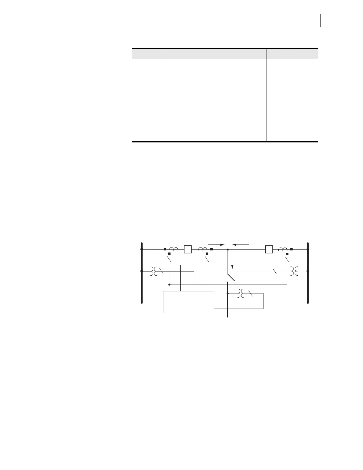
Set ESS to 4 for circuit breaker-and-a-half applications using combined
current input IW. Figure 1.8 illustrates this application along with the
corresponding current and voltage sources. Current input IX provides circuit
breaker failure protection for Circuit Breaker 1; the corresponding CTs are
located on the line-side of Circuit Breaker 1. The relay calculates the current
flowing through Circuit Breaker 2 (I
CB2
= IW + IX= I
CB1
+ I
CB2
+ IX = I
CB1
+ I
CB2
- I
CB1
) to provide independent circuit breaker failure for Circuit
Breaker 2.
Figure 1.8 ESS := 4, Double Circuit Breaker Configuration
Table 1.8 ESS := 3, Current and Voltage Source Selection
Setting Description Entry Comments
NUMBK Number of Circuit Breakers in Scheme (1, 2) 2
LINEI Line Current Source (COMB) COMB Automatic
ALINEI Alternate Line Current Source (NA) NA Automatic
ALTI Alternate Current Source (SEL
OGIC Equation) NA Hidden
BK1I Breaker 1 Current Source (IW) IW Automatic
BK2I Breaker 2 Current Source (IX) IX Automatic
IPOL Polarizing Current (NA) NA Automatic
ALINEV Alternate Line Voltage Source (VZ, NA) NA
ALTV Alternate Voltage Source (SEL
OGIC Equation) NA Hidden
SEL-421 Relay
BUS 1 BUS 2
CB1 CB2
33
3
3
IW
IX
VAZ
VY
VBZ
1
1
Analog Input
IW+IX
IW
IX
VY
VAZ
VBZ
Function
CB2 protection
Line protection
CB1 protection
Line protection
Synchronism check Circuit Breaker 1
Synchronism check Circuit Breaker 2
I
CB1
I
CB2
I
LINE