R.3.17
Date Code 20111215 Reference Manual SEL-421 Relay
SELOGIC Control Equation Programming
SELOGIC Control Equation Elements
Automation Latch Bits
The automation latch bits, ALT01–ALT32, are available in automation free-
form settings. Write free-form SEL
OGIC control equations to set and reset
these bits. As with protection latch bits, the relay stores automation latch bits
in nonvolatile memory and preserves these through a relay power cycle and
group change operations. With protection latch bits, you can implement Set
and Reset programming for each protection settings group. Automation
SEL
OGIC control equation programming, however, has only one programming
area active for all protection settings groups.
The relay evaluates the latch bit value at the end of the automation free-form
SEL
OGIC control equation execution cycle. The values for Reset (ALTnnR)
and Set (ALTnnS) remain unchanged until evaluation of all SEL
OGIC control
equations, when the relay evaluates the latch (ALTnn). For example, if you
have multiple SEL
OGIC control equations for set, the last equation in the
automation free-form area dominates, and the relay uses this equation to
evaluate the latch.
Conditioning Timers
Use conditioning timers to condition Boolean values. Conditioning timers
either stretch incoming pulses or allow you to require that an input take a state
for a certain period before reacting to the new state. Conditioning timers are
available in the protection free-form area, as shown in Table 3.13.
Conditioning timers have the three input parameters and one output shown in
Tab le 3.14.
A conditioning timer output turns on and becomes logical 1, after the input
turns on and the Pickup Time expires. An example timing diagram for a
conditioning timer, PCT01, with a Pickup Time setting greater than zero and a
Dropout Time setting of zero is shown in Figure 3.3. In the example timing
diagram, the Input, PCT01IN, turns on and the timer Output, PCT01Q, turns
on after the Pickup Time, PCT01PU, expires. Because the Dropout Time
setting is zero, the Output turns off when the Input turns off.
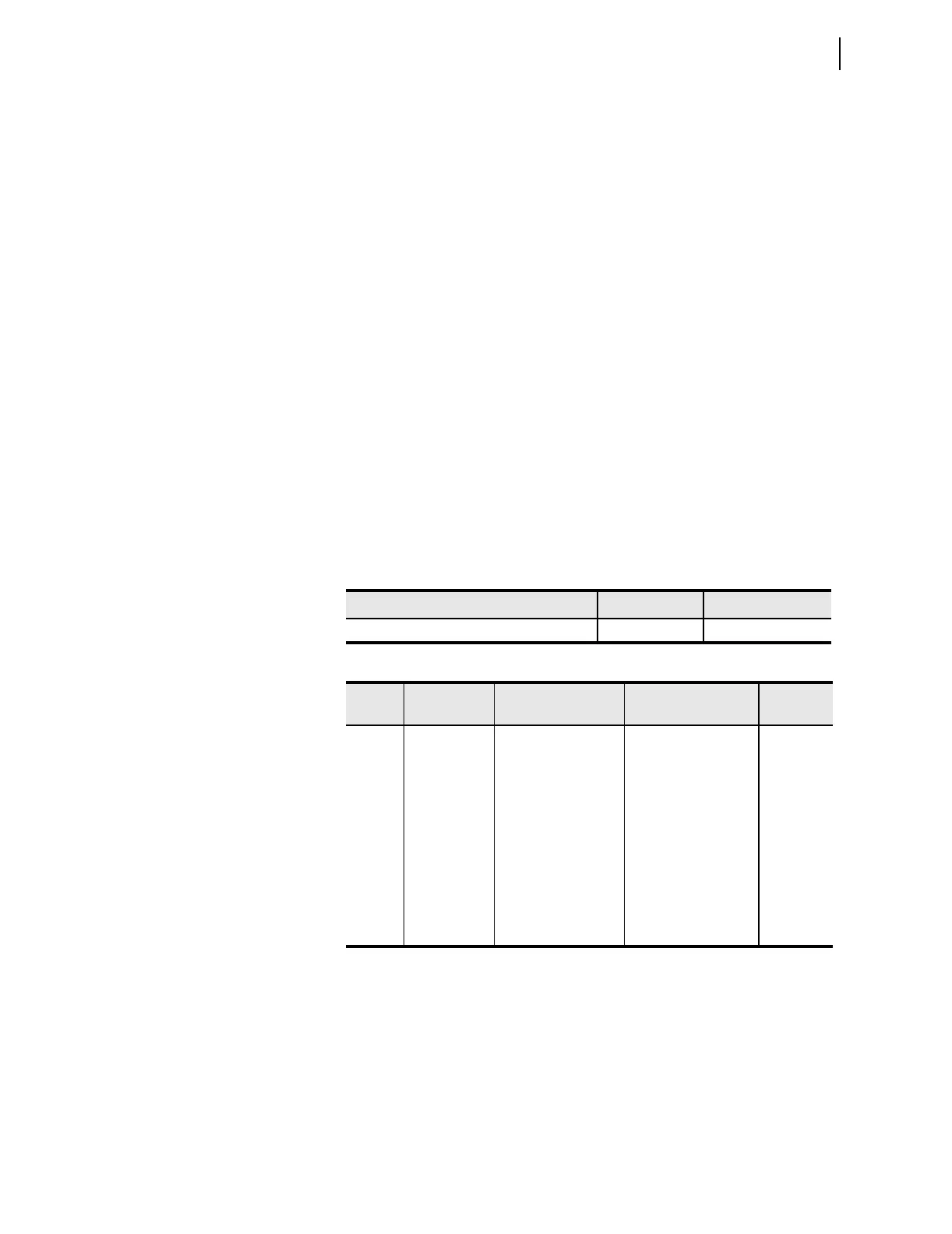
Table 3.13 Conditioning Timer Quantities
Type Quantity Name Range
Protection free-form conditioning timers 32 PCT01–PCT32
Table 3.14 Conditioning Timer Parameters
Type Item Description Setting
Name
Examples
Input Input Value that the relay
times
Boolean SELOGIC
control equation set-
ting
PCT01IN
Input Pickup Time Time that the input
must be on before the
output turns on
Time value in cycles PCT01PU
Input Dropout Time Time that the output
stays on after the
input turns off
Time value in cycles PCT01DO
Output Output Timer output Value for Boolean
SEL
OGIC control
equations
PCT01Q