R.4.3
Date Code 20111215 Reference Manual SEL-421 Relay
Communications Interfaces
Serial Communication
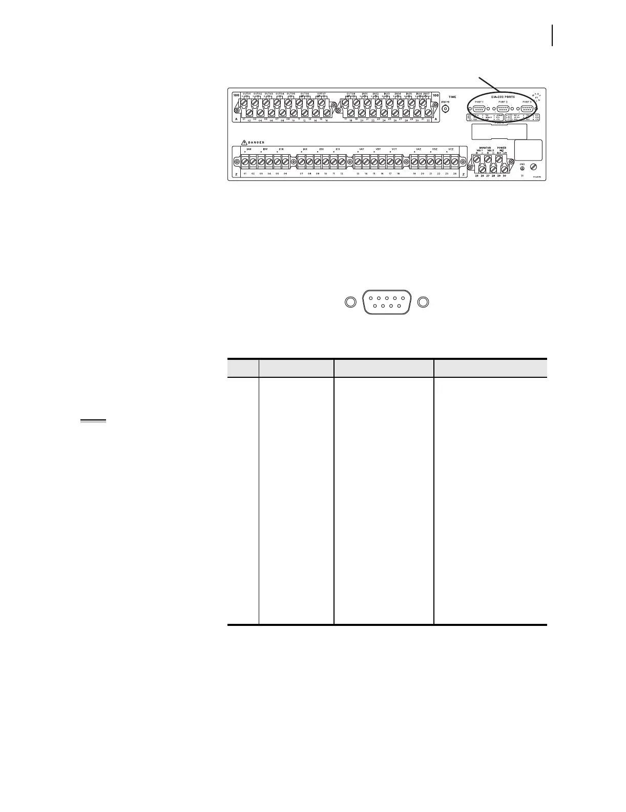
Figure 4.2 SEL-421 3U Rear-Panel Layout
The EIA-232 ports are standard female 9-pin connectors with the pin
numbering shown in Figure 4.3. The pin functions are listed in Tabl e 4.2 . See
the manual section listed in Table 4.1 for a description of how the relay uses
these pins with your specific protocol. Pin 1 can provide power to an external
device. See Serial Port Jumpers on page U.2.21 for more information on
installing the jumper to provide voltage on Pin 1.
Figure 4.3 EIA-232 Connector Pin Numbers
EIA-232
Communications
Cables
For most installations, you can obtain information on the proper EIA-232
cable configuration from the SEL-5801 Cable Selector Program. Using the
SEL-5801 software, you can choose a cable by application. The software
provides the SEL cable number with wiring and construction information, so
you can order the appropriate cable from SEL or construct one. If you do not
see information for your application, please contact SEL and we will assist
you. You can obtain a copy of the SEL-5801 software by contacting SEL or
from the SEL website www.selinc.com.
Table 4.2 EIA-232 Pin Assignments
Pin Signal Name Description Comments
1 5 Vdc Modem power Jumper selectable on PORT1–
PORT 3. No connection on
PORT F.
2 RXD Receive data
3 TXD Transmit data
4 +IRIG-B Time code signal positive PORT 1 only. No connection on
PORT F, PORT 2, and PORT 3.
5 GND Signal ground Also connected to chassis
ground.
6 –IRIG-B Time code signal negative PORT 1 only. No connection on
PORT F, PORT 2, and PORT 3.
7 RTS Request to send
8
8
CTS
TX/RX CLK (for
SPEED:= SYNC,
only available
when PROTO:=
MBA or MBB)
Clear to send (input)
Transmit and receive
clock (input)
Rear-panel serial ports only
9 GND Chassis ground
NOTE: Pins 5 and 9 are not intended
to provide a chassis ground
connection. See Section 2:
Installation in the User’s Guide.