R.2.61
Date Code 20111215 Reference Manual SEL-421 Relay
Auto-Reclosing and Synchronism Check
Synchronism Check
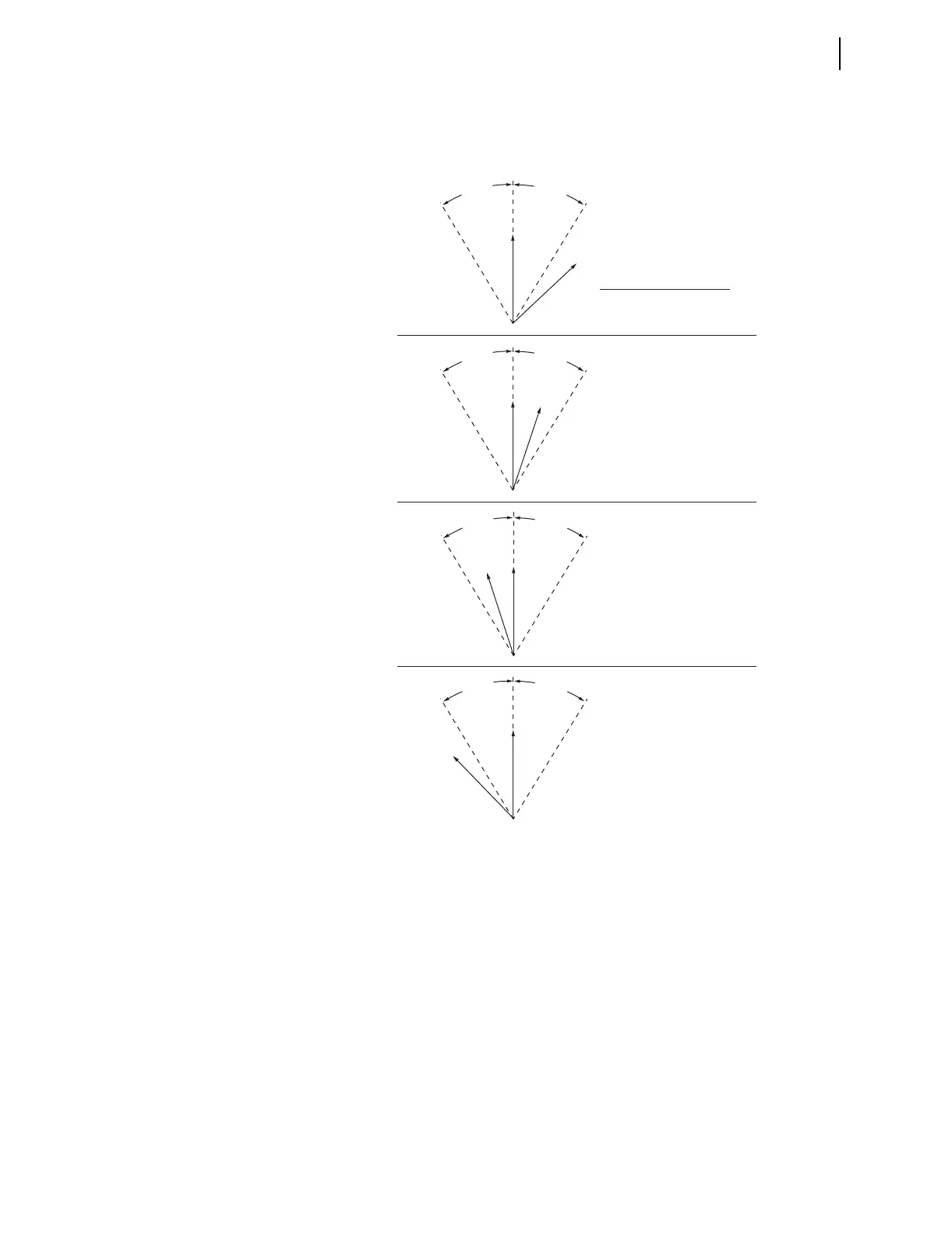
The out-of-synchronism phase angles in Figure 2.29 appear dramatic for a “no
slip” paralleled system. This is for illustrative purposes; these angles are not
usually this large in actual systems.
Figure 2.29 “No Slip” System Synchronism-Check Element Output
Response
Slip Frequency and SFZBK1
Relay Word bit SFZBK1 (BK1 Slip Frequency less than 0.005 Hz) also asserts
to logical 1, indicating a “no slip” condition across Circuit Breaker BK1. In
other words, the slip frequency is less than 0.005 Hz (|f
S1
–f
P
| < 0.005 Hz).
Synchronism-Check Element Output Effects
Note that element outputs 25W1BK1 and 25A1BK1 operate identically in all
of the “no slip” cases in Figure 2.29 (both assert to logical 1 or deassert to
logical 0).
V
P
(a)
(b)
(c)
(d)
V
S1
V
P
V
S1
V
P
V
S1
V
P
V
S1
No slip (paralleled system)
Response of synchronism-check
element outputs (Relay Word Bits):
25W1BK1 = logical 1
25A1BK1 = logical 1
25W1BK1 = logical 1
25A1BK1 = logical 1
25W1BK1 = logical 0
25A1BK1 = logical 0
25W1BK1 = logical 0
25A1BK1 = logical 0
A
N
G
1
B
K
1
A
N
G
1
B
K
1
A
N
G
1
B
K
1
A
N
G
1
B
K
1
A
N
G
1
B
K
1
A
N
G
1
B
K
1
A
N
G
1
B
K
1
A
N
G
1
B
K
1