R.2.51
Date Code 20111215 Reference Manual SEL-421 Relay
Auto-Reclosing and Synchronism Check
Synchronism Check
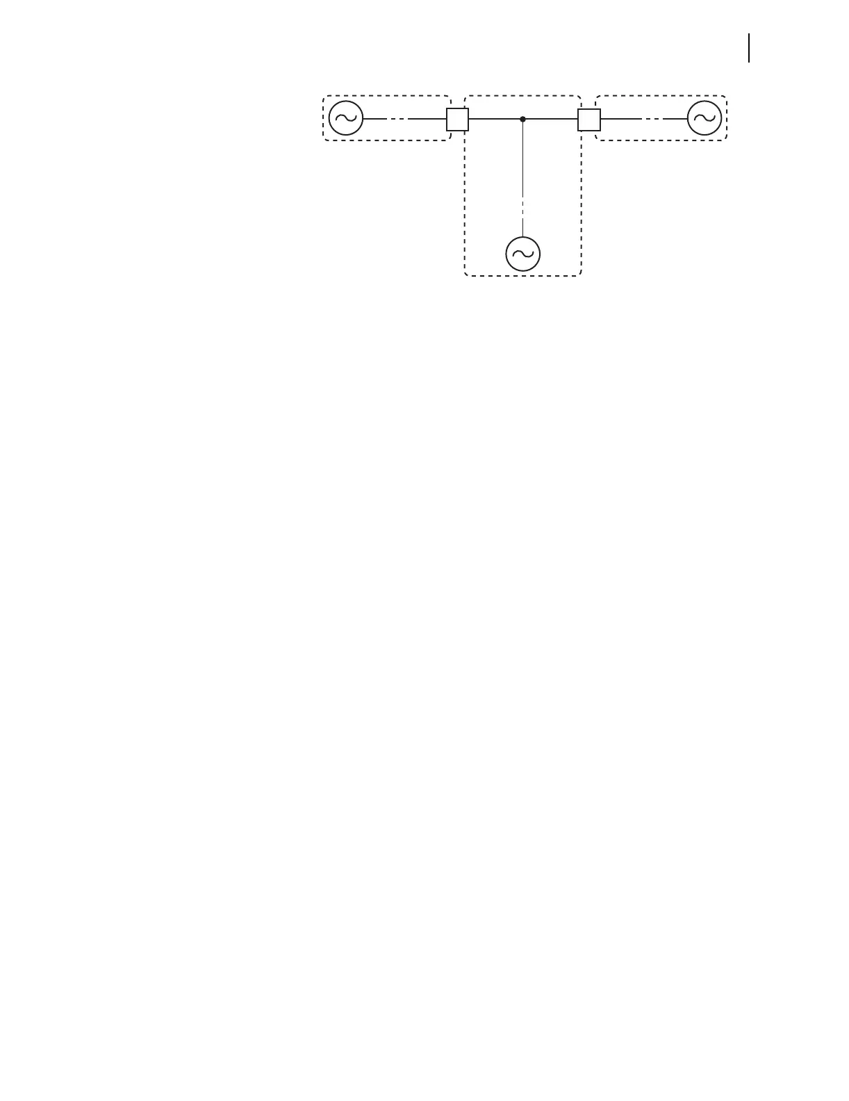
Figure 2.19 Partial Breaker-and-a-Half or Partial Ring-Bus Breaker
Arrangement
Paralleled and
Asynchronous
Systems
Figure 2.19 shows remote sources for each section. Often, a portion of the
power system is paralleled beyond the open Circuit Breakers BK1 and BK2;
the remote sources are really the same aggregate source. If the aggregate
source is much closer to one side of the open circuit breaker than the other,
there is a noticeable voltage angle difference across the system (it is not
simply zero degrees). The corresponding angular separation results from load
flow and the impedance of the parallel system.
Here is a simple method to calculate the voltage angle across the circuit
breaker if a load flow study is not readily available. Be aware that the angle
resulting from load flow is typically larger than the angle calculated in
Equation 2.1 and shown in Figure 2.20.
Voltage Angle Difference Estimate
The propagation of the electric signal at nearly the speed of light causes a
voltage angle to appear across the open circuit breaker. Figure 2.20 illustrates
the angle difference. Note that the aggregate source is near one end of the
open circuit breaker, but is 80 kilometers away from the other end. The angle
difference is calculated in Equation 2.1:
Equation 2.1
Therefore, even though this system is paralleled beyond the open circuit
breaker, a 6-degree voltage angle difference results across the circuit breaker
(even with no load flow through the parallel path).
You must consider this angle difference when setting the synchronism-check
element for a paralleled system. In this example, do not set the voltage angle
difference setting to less than 15–20 degrees nominal. A paralleled system
does not imply a zero degree voltage angle difference at every measuring
point.
80 km
s
300x10
3
km
-------------------------------
60 cyc
s
----------------
360
cyc
-----------
6• • •