R.7.17
Date Code 20111215 Reference Manual SEL-421 Relay
Synchrophasors
Settings for Synchrophasors
TREA1, TREA2, TREA3, TREA4, and PMTRIG
Defines the programmable trigger bits as allowed by IEEE C37.118.
Each of the four Trigger Reason settings, TREA1–TREA4, and the PMU
Trigger setting, PMTRIG, are SEL
OGIC control equations in the Global
settings class. The SEL-421 evaluates these equations and places the results in
Relay Word bits with the same names: TREA1–TREA4, and PMTRIG.
The trigger reason equations represent the Trigger Reason bits in the STAT
field of the data packet. After the trigger reason bits are set to convey a
message, the PMTRIG Equation should be asserted for a reasonable amount
of time, to allow the synchrophasor processor to read the TREA1–TREA4
fields.
The IEEE C37.118 standard defines the first eight of 16 binary combinations
of these trigger reason bits (bits 0–3).
The remaining eight binary combinations are available for user definition.
The SEL-421 does not automatically set the TREA1–TREA4 or PMTRIG
Relay Word bits—these bits must be programmed.
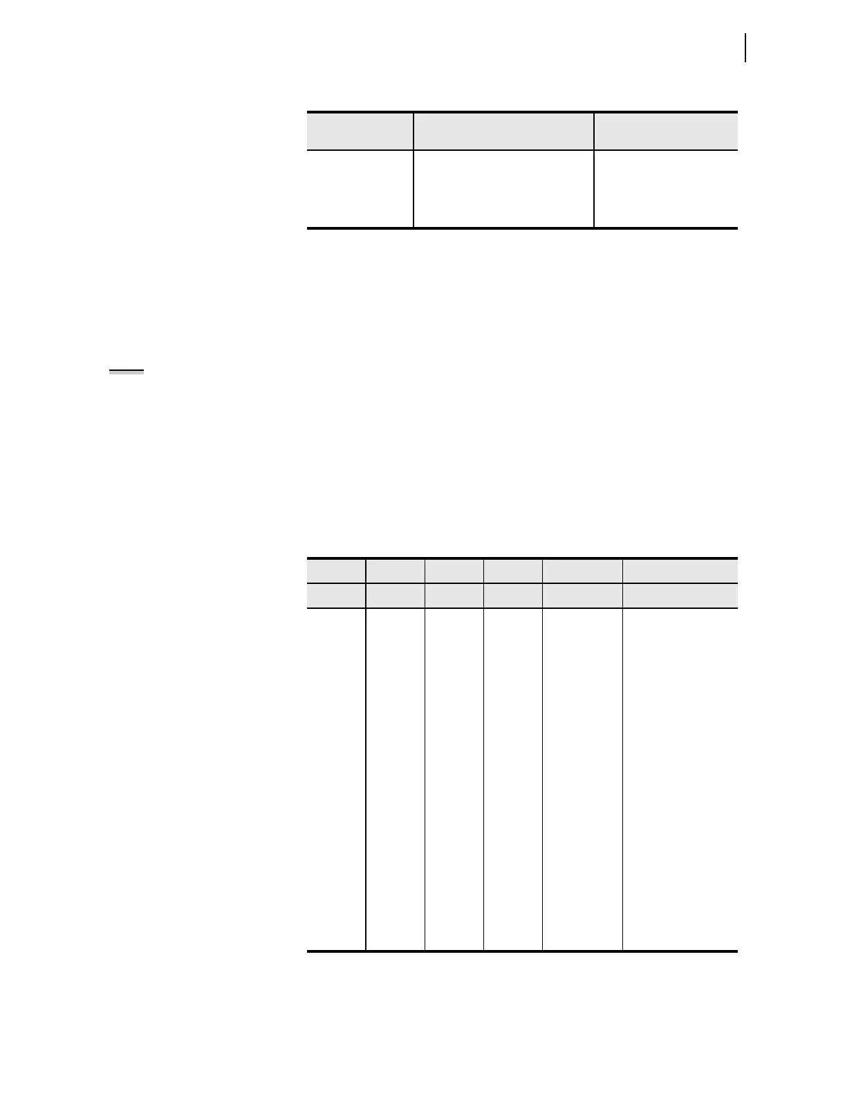
Table 7.7 User-Defined Digital Status Words Selected by the NUMDSW Setting
NUMDSW Setting Digital Status Words Sent
Total Number of Bytes
Used for Digital Values
0 None 0
1 [PSV64, PSV63.....PSV49] 2
2 [PSV64, PSV63.....PSV49]
[PSV48, PSV47.....PSV33]
4
Table 7.8 PM Trigger Reason Bits—IEEE C37.118 Assignments
TREA4 TREA3 TREA2 TREA1 Meaning
a
a
When PMTRIG is asserted. The terminology comes from IEEE C37.118.
(bit 3) (bit 2) (bit 1) (bit 0) Hexadecimal
0 0 0 0 0x00 Manual
0 0 0 1 0x01 Magnitude Low
0 0 1 0 0x02 Magnitude High
0 0 1 1 0x03 Phase Angle Diff.
0 1 0 0 0x04 Frequency High/Low
0 1 0 1 0x05 df/dt High
0 1 1 0 0x06 Reserved
0 1 1 1 0x07 Digital
1 0 0 0 0x08 User
1 0 0 1 0x09 User
1 0 1 0 0x0A User
1 0 1 1 0x0B User
1 1 0 0 0x0C User
1 1 0 1 0x0D User
1 1 1 0 0x0E User
1 1 1 1 0x0F User
NOTE: The PM Trigger function is
not associated with the SEL-421
Event Report Trigger ER, a SEL
OGIC
control equation in the Group
settings class.