R.1.16
SEL-421 Relay Reference Manual Date Code 20111215
Protection Functions
Time-Error Calculation
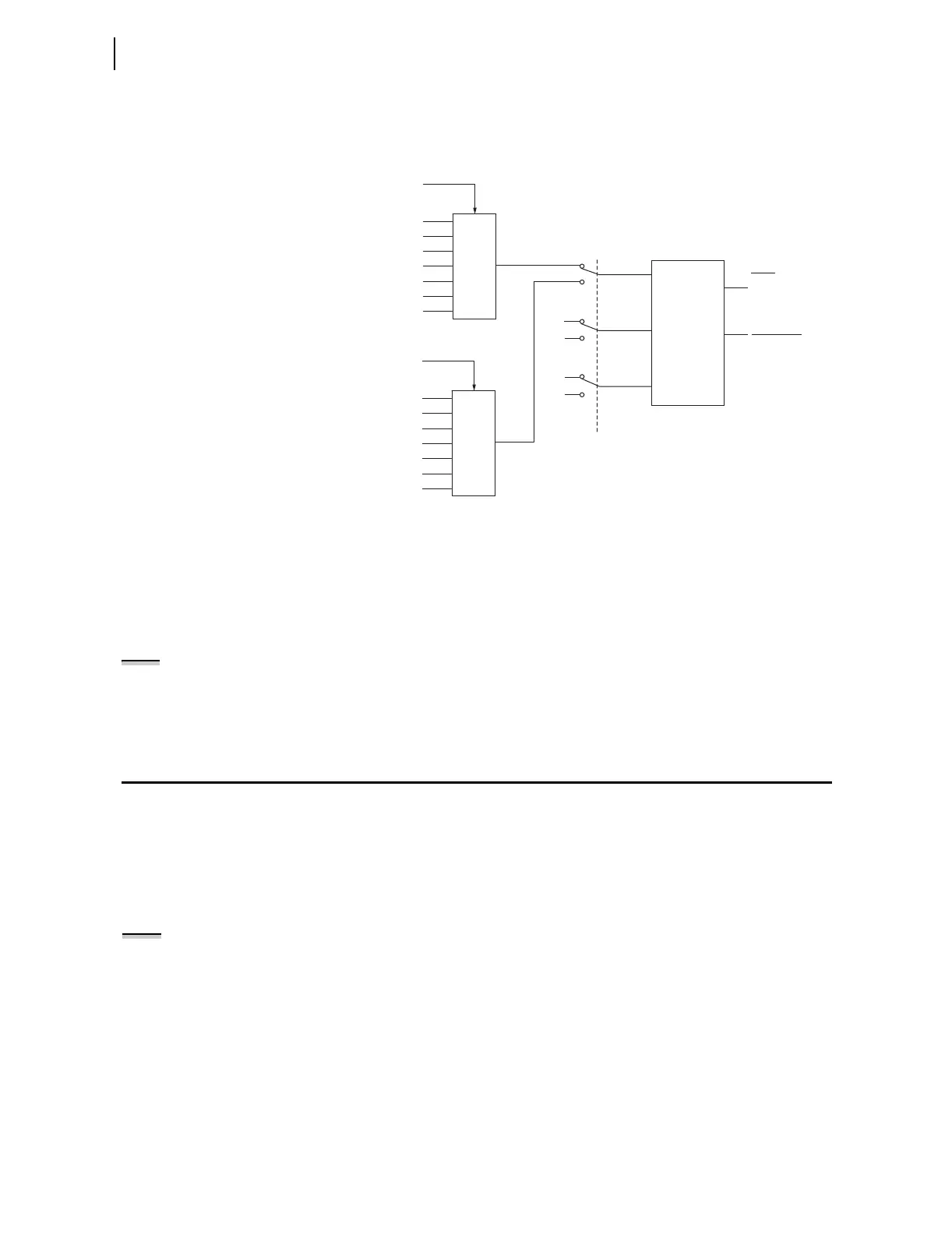
signals dropout, the measured frequency reverts to the nominal frequency
(Global setting NFREQ := 50 or 60 Hz) after approximately two seconds. In
this situation, Relay Word bit FREQOK deasserts.
Figure 1.12 Frequency Estimation for Protection Functions
Frequency Estimation
Provided by
Synchrophasor
The frequency and rate of change of frequency is estimated using
synchrophasors. These measurements are included in the synchrophasor data
packet and can be viewed by the MET PM command. The rate of change of
frequency (DFDT) is also included as an analog quantity that can be used in
SEL
OGIC equation. Note that DFDT is not available if synchrophasors are not
enabled or active.
NOTE: The DFDT calculation is only
performed when Global setting
EPMU := Y.
Time-Error Calculation
Description and
Settings
The Time-Error calculation function in the SEL-421 measures the amount of
time that an ac clock running from the same line frequency measured by the
relay would differ from a reference clock. The relay integrates the difference
between the measured power system frequency and the nominal frequency
(Global setting NFREQ) to create a time-error analog quantity, TE.
A correction feature allows the present time-error estimate (TE) to be
discarded, and a new value (TECORR) loaded when SEL
OGIC control
equation LOADTE asserts. For example, if the TECORR value is set to zero,
and then LOADTE is momentarily asserted, the TE analog quantity will be set
to 0.000 seconds.
The TECORR analog quantity can be pre-loaded by the TEC Command (see
TEC on page R.9.51), or via DNP3, object 40, 41 index 01 (see Table 6.10 on
page R.6.17). In either case, Relay Word bit PLDTE asserts for approximately
1.5 cycles to indicate that the preload was successful.
A separate SEL
OGIC control equation, STALLTE, when asserted, causes time-
error calculation to be suspended.
VCX
VF01
VF11
VF02
V1
V2
V3
Frequency
Estimation
Switches in position 1
if EAFSRC = logical 0,
otherwise in position 2
VF03
VF12
VF13
VAY
VBY
VCY
ZERO
ZERO
1
2
1
2
1
2
VF01 Selection
VAX
VBX
Switch
VCX
VAY
VBY
VCY
VF11 Selection
VAX
VBX
Switch
FREQOK
FREQ
Analog
Quantities
Relay
Word
Bit
NOTE: The LOADTE SELOGIC
equation is processed once per cycle.
A momentary assertion must be
conditioned to be at least one cycle
in duration. A rising edge operator
(R_TRIG) should not be used in the
LOADTE setting.