R.7.7
Date Code 20111215 Reference Manual SEL-421 Relay
Synchrophasors
Synchrophasor Measurement
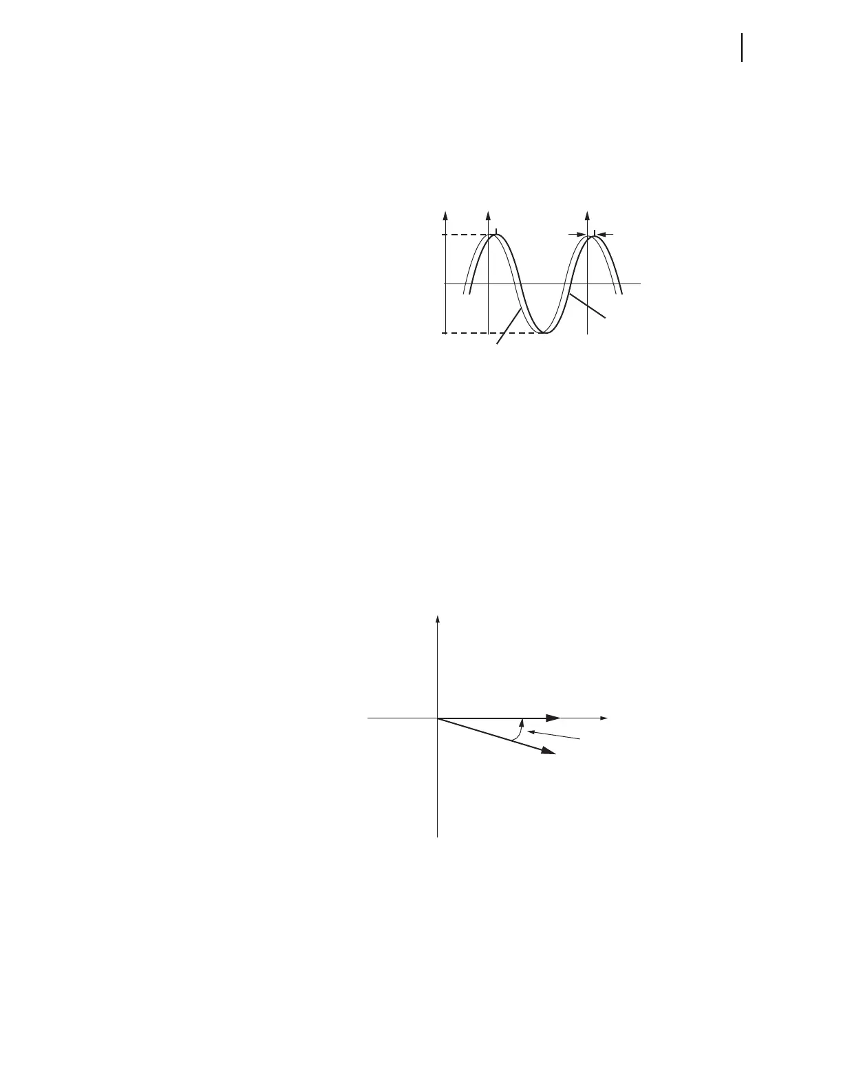
The instrumentation transformers (pts or cts) and the interconnecting cables
may introduce a time shift in the measured signal. Global settings VCOMP,
IWCOMP, and IXCOMP, entered in degrees, are added to the measured
phasor angles to create the corrected phasor angles, as shown in Figure 7.10,
Figure 7.11, and Equation 7.1. The VCOMP, IWCOMP, and IXCOMP
settings may be positive or negative values.
Figure 7.10 Waveform at Relay Terminals May Have a Phase Shift
Equation 7.1
If the time shift on the pt measurement path t
pt
= 0.784 ms and the nominal
frequency, freq
nominal
= 60Hz, use Equation 7.2 to obtain the correction angle:
. Equation 7.2
Figure 7.11 Correction of Measured Phase Angle
For a sinusoidal signal, the phasor magnitude is calculated as shown in
Equation 7.3. The phasors are rms values scaled in primary units, as
determined by Group settings PTRY or PTRZ (for the presently selected line
voltage source, VY or VZ, respectively), CTRW, and CTRX (for the IW and
IX current sources). The SEL-421 then creates the summation quantities IS =
IW + IX phase currents, and calculates the positive-sequence voltage
V1LPM_ and currents I1WPM_, I1XPM_, and I1SPM_.
94.851
–94.851
Δ
t
pt
0t
V
A
(t)
measured
waveform
actual
waveform
Compensation Angle
t
pt
1
freq
nominal
----------------------------
----------------------------------
360• =
t
pt
freq
nominal
360• • =
0.784 10
3–
s60s
1–
360• • • 16.934=
Imaginary
Real
M
M
V
A measured
V
A corrected
Compensation Angle