R.1.2
SEL-421 Relay Reference Manual Date Code 20111215
Protection Functions
Current and Voltage Source Selection
➤ Trip Logic on page R.1.105
➤ Circuit Breaker Failure Protection on page R.1.115
Current and Voltage Source Selection
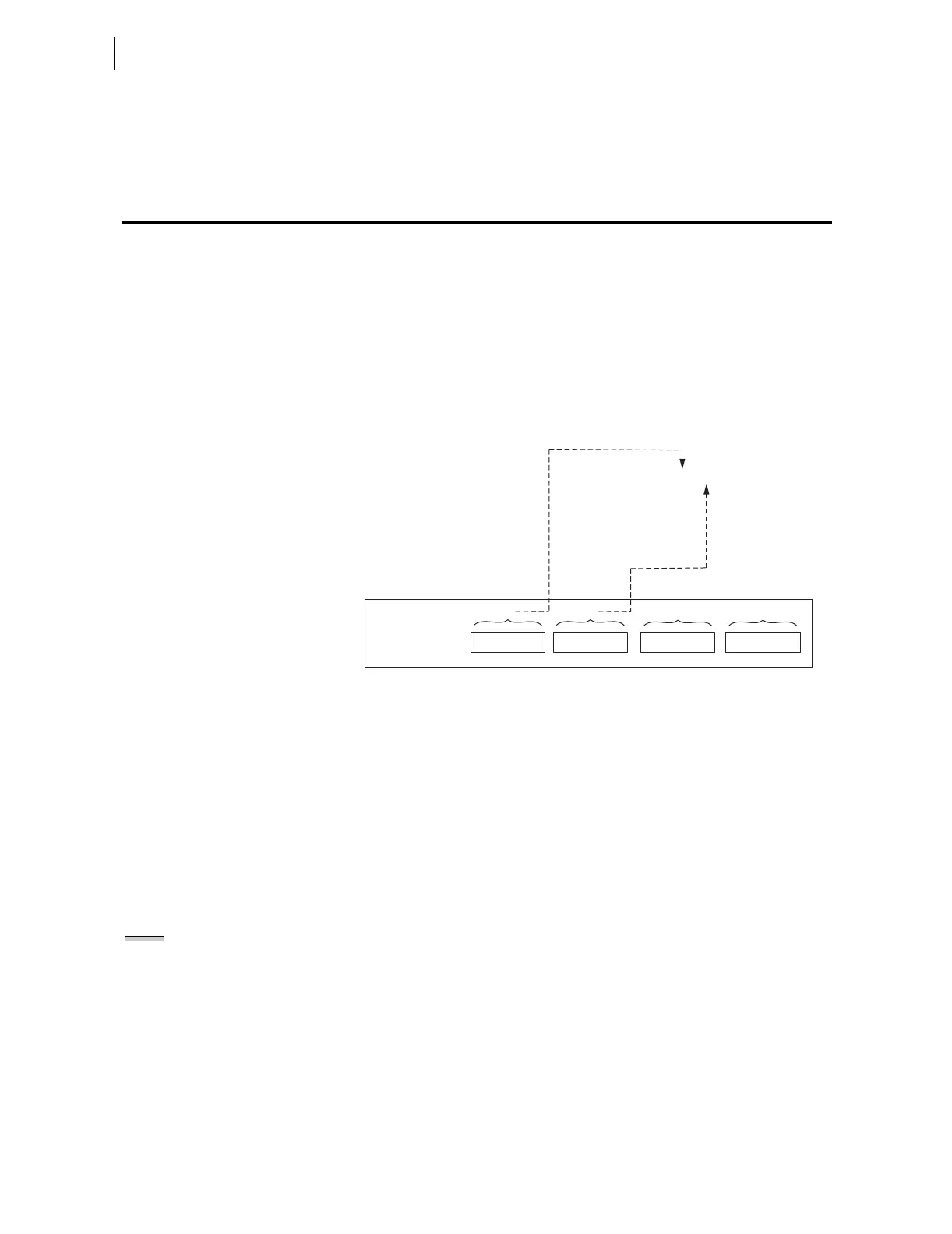
The SEL-421 has two sets of three-phase current inputs (IW and IX) and two
sets of three-phase voltage inputs (VY and VZ), as shown in Figure 1.1.
Currents IW and IX are also combined internally (COMB = IW + IX) on a
per-phase basis and made available as the line current option for protection,
metering, etc. You can select the current and voltage sources for a wide variety
of applications, using the global settings in Table 10.14 on page R.10.9. The
SEL-421 provides five default application settings (ESS := N, 1, 2, 3, or 4)
that cover common applications (see Table 1.1). When you set ESS := Y, you
can set the current and voltage sources for other applications (see Tab le 1.2
and Table 1.3). ESS settings examples are given later in this subsection.
Figure 1.1 Current and Voltage Source Connections for the SEL-421 Relay
Current Source
Switching
Figure 1.2 through Figure 1.4 show the basic application of some of these
settings. Figure 1.2 shows an alternate breaker that can be substituted for the
main breaker (bus switching details not shown). Normally, current IW (main
breaker) is used as the line current source. But, if the alternate breaker
substitutes for the main breaker, then current IX is used as the line current
source, instead. SEL
OGIC setting ALTI controls the switching between
currents IW and IX as the line current source (assert setting ALTI to switch to
designated alternate line current ALINEI := IX). Alternate line current source
settings ALINEI and ALTI are not used often and thus are usually set to NA.
Setting ALTI is automatically hidden and set to NA if ALINEI := NA (no line
current switching can occur).
Figure 1.3 shows combined currents IW and IX (see COMB = IW + IX in
Figure 1.1) set for line protection, metering, etc. (LINEI := COMB). In order
to combine these currents correctly inside the relay to produce the effective
line current, the current transformer ratios for the respective IW and IX
secondary circuits have to be the same.
Figure 1.4 shows the assignment of breaker currents for up to two circuit
breakers. These assigned breaker currents are used in breaker monitoring and
breaker failure functions. These same breaker currents can also be assigned as
line currents (e.g., line current assignment LINE1 := IW in Figure 1.2).
SEL-421 rear panel
(partial)
COMB = IW + IX
(combined
current
source
for line)
Current
source
(for breaker
and/or
for line)
IAW IBW ICW
IW
IAX IBX ICX
IX
Current
source
(for breaker
and/or as
alternate
for line)
VAZ VBZ VCZ
VZ
Voltage source
(alternate)
VAY VBY VCY
VY
Voltage source
NOTE: If a current source is set to
"combine" (e.g., LINEI := COMB), then
the current transformer ratios for
the respective IW and IX secondary
circuits have to be the same (i.e.
group settings CTRW = CTRX).