R.3.18
SEL-421 Relay Reference Manual Date Code 20111215
SELOGIC Control Equation Programming
SELOGIC Control Equation Elements
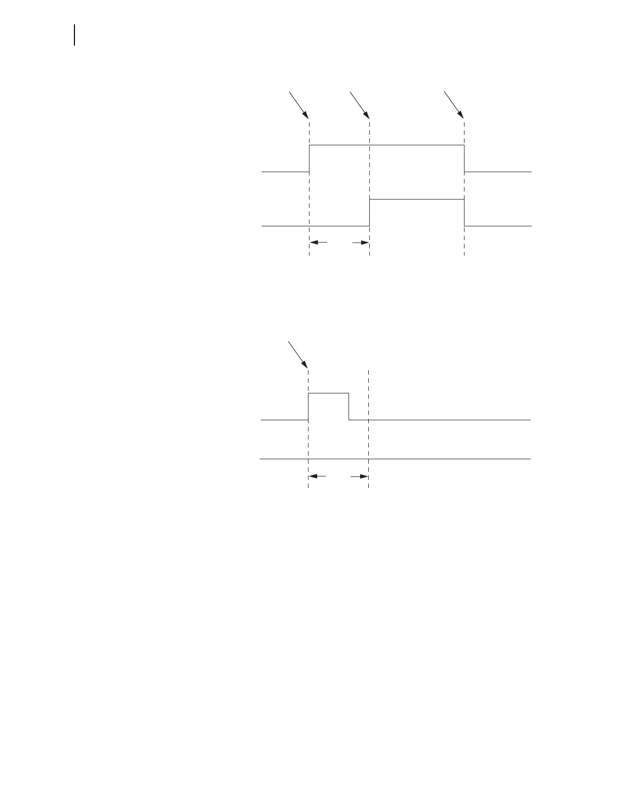
Figure 3.3 Conditioning Timer With Pickup and No Dropout Timing Diagram
If the Pickup Time is not satisfied, the timer Output never turns on, as
illustrated in Figure 3.4.
Figure 3.4 Conditioning Timer With Pickup Not Satisfied Timing Diagram
A conditioning timer output turns off when the input turns off and the Dropout
Time expires. An example timing diagram for a conditioning timer, PCT02,
with a Pickup Time setting of zero and a Dropout Time setting greater than
zero is shown in Figure 3.5. Because the Pickup Time, PCT02PU, setting is
zero, the Output, PCT02Q, turns on when the Input, PCT02IN, turns on. The
Output turns off after the Input turns off and the Dropout Time, PCT02DO,
expires.
PCT01IN
PCT01Q
Input Changes
from 0 to 1
Input Changes
from 1 to 0
Pickup
Time
PCT01PU
Pickup Time
Expires
PCT01IN
PCT01Q
Input Changes
from 0 to 1
Pickup
Time
PCT01PU