R.2.53
Date Code 20111215 Reference Manual SEL-421 Relay
Auto-Reclosing and Synchronism Check
Synchronism Check
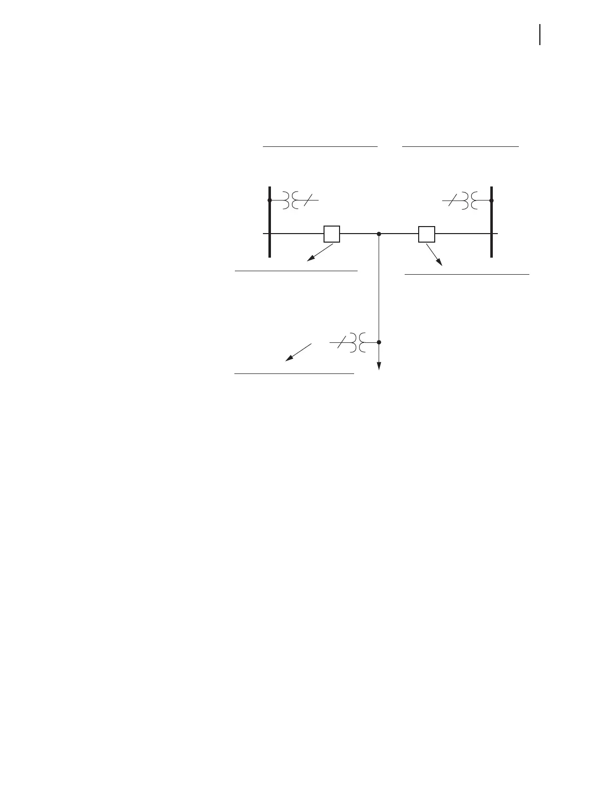
Figure 2.22 shows the correspondence between the synchronism-check
settings and the two-circuit breaker application example. All of these settings
are listed in Section 10: Settings. The following subsections explain these
settings and include an explanation of Alternative Synchronism-Check
Voltage Source 2 settings (see Figure 2.32).
Figure 2.22 Synchronism-Check Settings
Synchronism-Check
Logic Outputs
Figure 2.23 shows the correspondence between synchronism-check logic
outputs (Relay Word bits) and the two-circuit breaker arrangement. These
Relay Word bits assert to logical 1 (e.g., 59VP equals logical 1) if true and
deassert to logical 0 (e.g., 59VS1 equals logical 0) if false. Table 2.26 lists
these Relay Word bits.
Bus 2
Bus 1
Line
BK2
BK1
Synchronism-Check Voltage Source 1
SYNCS1 — designate voltage input
KS1M — adjust magnitude to reference
KS1A — adjust angle to reference
Synchronism-Check Voltage Reference
SYNCP — designate voltage input
25VL — voltage window/low threshold
25VH — voltage window/high threshold
Synchronism-Check Across Breaker BK2
25SFBK2 — max. slip frequency
ANG1BK2 — max. angle difference 1
ANG2BK2 — max. angle difference 2
TCLSBK2 — breaker close time
BSYNBK2 — block synch check (SEL
OGIC)
Synchronism-Check Across Breaker BK1
25SFBK1 — max. slip frequency
ANG1BK1 — max. angle difference 1
ANG2BK1 — max. angle difference 2
TCLSBK1 — breaker close time
BSYNBK1 — block synch check (SEL
OGIC)
Synchronism-Check Voltage Source 2
SYNCS2 — designate voltage input
KS2M — adjust magnitude to reference
KS2A — adjust angle to reference
1
3
1
. . .
. . .
. . .