Configuring the fieldbus
7.7 Communication over CANopen
Inverter with CU230P-2 Control Units
Operating Instructions, 11/2013, FW V4.6.6, A5E02430659B AG
199
The inhibit time defines the minimum interval between two transmissions.
Synchronous data transmission
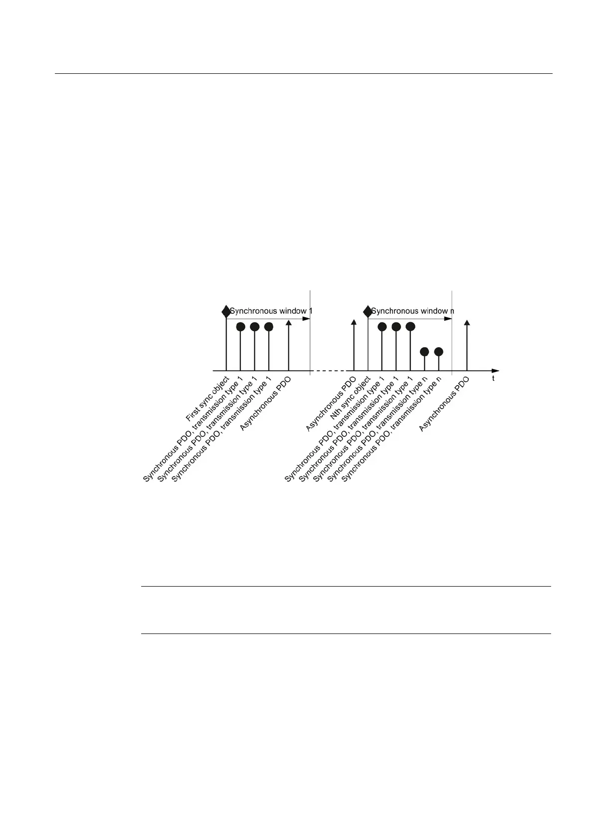
A periodic synchronization object (SYNC object) ensures that the devices on the CANopen
bus remain synchronized during transmission.
Each PDO transferred as synchronization object must include a "transmission type" 1 ... n:
● Transmission type 1: PDO in each SYNC cycle
● Transmission type n: PDO in every n-th SYNC cycle
The following diagram shows the principle of synchronous and asynchronous transmission:
Figure 7-21 Principle of synchronous and asynchronous transmission
For synchronous TPDOs, the transmission mode also identifies the transmission rate as a
factor of the SYNC object transmission intervals.
The CAN controller transfers data from synchronous RPDOs that it received after a SYNC
signal only after the next SYNC signal to the inverter.
Note
The SYNC signal synchronizes only the communication on the CANopen bus and not
functions in the inverter, e.g. the clock times of the speed cont
rol.

 Loading...


